How to read microphone specifications
Microphone specifications are generated to inform users about the basic features of the mic and how the microphone fits your needs – as well as your equipment’s.
It is important to understand how to interpret microphone specifications. In most cases, specifications can be measured or calculated in several ways, although the IEC 60.268-4 standard serves as the common ground. In addition, when comparing specifications, the same technical term is sometimes interpreted differently from brand to brand.
With a focus on the DPA microphone specification sheet, this article is designed to help evaluate specs meaningfully.
The decibel (dB) scale
The basis for most microphone specifications is the decibel scale. The dB scale is logarithmic and applied because most human senses – including hearing – are close to being logarithmic. Using a logarithmic scale means that there is a fixed ratio between each unit of the scale (e.g., ratio 10, the units are: 1-10-100-1000, etc. - or ratio 2, the units are: 1-2-4-8-16, etc.) This logarithmic scaling applies to many of the electrical or acoustical measures, which specify microphones (i.e., Volt, Pascal, Watt, Ampere, etc.).
The advantage of this scale is that 1 dB is about the smallest change of level you can hear. 3 dB is a clear audible change. 10 dB is subjectively perceived as a doubling or a halving. By and large, each step on the scale is perceived as equal in size. The largest dB number you will find in real life is <200.
The dB-scale is a relative scale. Thus, you can express any change in dB. A change of 0 dB is no change at all. Any positive dB value indicates a positive change (the value is now higher than before). Any negative dB number indicates a negative change (the value now is lower than before).
You can make dB an absolute scale by applying a reference — for instance, the sound pressure level, the reference being 20 μPa. Now, 0 dB means that sound pressure is present, and it is approximately 20 μPa (the threshold of hearing at mid-frequencies). Describing the level of sound pressure “dB re 20 μPa” also can be written as “dB SPL” (decibel, Sound Pressure Level).
For electrical measurements, another reference is 1 Volt, written as “0 dBV” or “0 dB re 1 Volt”. This absolute value applies, for instance, to the specification of microphone sensitivity.
Directional pattern
The directional pattern is a graphic way to show the acceptance angle of a microphone.
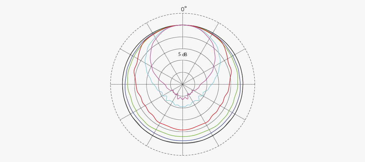
One feature of microphones is directionality, which can be expressed with the help of a polar plot. The polar plot is based on a concentric-circle grid. Each circle represents a dB level, usually starting with 0 dB at the outer circle. A reference point, marked as 0°, is defined at the top of the outer circle. The 0° indicates the microphone's on-axis direction.
All measured data are normalized at 0°. It means that even if the microphone’s sensitivity may differ at different frequencies (uneven frequency response), at 0° they align at 0 dB (the graph's level is raised or lowered to achieve this alignment of the curves). Each shift between emphasized circles indicates a 5 dB step typically, unless stated otherwise. In this way, you will be able to determine how much the recorded sound is attenuated in any off-axis direction.
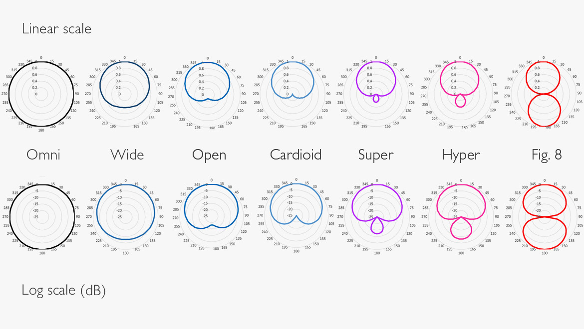
It is common to name the directionality of a microphone by the pattern it exhibits in the polar plot:
Omnidirectional: The response curve follows the outer circle all the way around. The microphone picks up sound evenly from all directions.
Wide cardioid (also called hypocardioid or subcardioid): Attenuation 3 dB @ ±90°. Attenuation 6 dB @ ±135°.
Open cardioid: Attenuation: 3 dB @ ±74.5°. Attenuation 6 dB ±105.5°.
Cardioid: The microphone picks up sound from the front and the sides, but not from the back. Attenuation 3 dB @ ±66°. Attenuation 6 dB @ ±90°.
Supercardioid: The microphone picks up sound from the front and a little from the rear, but is deaf to sound at approximately ±135°. Attenuation 3 dB @ 58°. Attenuation 6 dB @ 78°.
Hypercardioid: The microphone picks up sound from the front and some from the rear, but is deaf to sound at approximately ±115°. Attenuation 3 dB @ 55°. Attenuation 6 dB @ 73°.
Figure-of-eight: The microphone picks up sound equally from the front and the rear, but not from the sides. Attenuation 3 dB @ 54°. Attenuation 6 dB @ 73°.
See polar plots below.
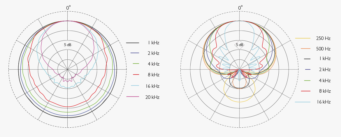
Often you will find only one polar figure describing a microphone. However, directivity may change with frequency. Thus, the polar patterns may look different at different frequencies, commonly defined by standard octave bands within the relevant frequency range of the microphone (i.e., 250 Hz, 500 Hz, 1 kHz, 2 kHz, 4 kHz, 8 kHz and 16 kHz).
The response curves should be smooth and symmetric to provide uncolored sound. Extreme peaks and valleys are undesirable, and the response curves should not cross. However, the curves presented may have been smoothed. The effect of curve smoothing may result in exceptionally smooth – sometimes too smooth – curves. Look closely at a curve to determine whether it originates from real measurements.
It is most common to measure directionality at a larger distance of 1-2 m (3-6 ft.). Even handheld microphones are measured at a distance like this. The explanation is that the voice is always recorded on axis, while the background sound (that should be attenuated) comes from all angles.
From the polar plot, you can also see how omnidirectional microphones usually become more directional at higher frequencies. Physically larger microphones exhibit more directionality at high frequencies due to pressure build-up at the front of the diaphragm.
The polar plot, in principle, only represents one “slice” of the directionality. However, in general, all pencil microphones exhibit a symmetric pattern around the axis of rotation due to the shape of the housing. Some microphones (non-symmetric microphone housing) may have horizontal and vertical patterns that are not identical.
Ref: IEC 60268-4 Sound System Equipment - Part 4: Microphones (2018)
clause 13.1: Directional pattern.
Principle of operation
The principle of operation refers to how the microphone diaphragm couples to the sound field.
The design of a microphone follows acoustical principles. In general, three principles govern the design of most microphones, including DPA microphones. The principles are pressure, pressure-gradient and interference-tube microphones.
Pressure microphones let the diaphragm receive sound from only one side. Pressure microphones have omnidirectional characteristics. These are the microphones we call “omnis”.
By design, pressure gradient microphones let the diaphragm receive sound from both sides, and this is how we obtain directivity. We call these microphones “cardioids”, “wide cardioids”, “open cardioids”, “supercardioids” or figure-of-eight.” Only the figure-of-eight should be called a pressure gradient microphone. The others (different variations of cardioids) are, in principle, combinations of pressure and pressure-gradient microphones. However, it is most common to categorize them all as gradients.

The interference tube is a construction that makes the microphone receive the on-axis sound and reject sound from the sides. Usually, the pressure-gradient principle and the interference tube are combined to achieve the best possible directivity, also at low frequencies.
Ref: IEC 60268-4 Sound System Equipment - Part 4: Microphones (2018)
clause 5.2: Type of microphone.
Microphone cartridge type
The cartridge is the type of transducer applied to the microphone. DPA microphones are predominantly built on the electret principle.
The cartridge is the element or transducer that transforms sound pressure into electricity. In the pro audio market, the two main types of transducers are (electro-) dynamic microphones and condenser microphones.
DPA manufactures condenser microphones. Most condensers need a polarization voltage to work. This polarization can be external or internal. DPA microphones are internally polarized or rather pre-polarized cartridges. The microphones, however, need a power supply, not for the capsule but for the built-in preamp.
So, most DPA microphones are described: Pre-polarized condenser. A few models are described: Condenser.
Ref: IEC 60268-4 Sound System Equipment - Part 4: Microphones (2018)
clause 5.1: Type of the transducer.
Microphone frequency response
The frequency response indicates the complete frequency range at which the microphone responds.
A frequency response expresses a microphone’s output as a function of frequency. It is usually evaluated by applying a sinusoidal acoustic signal in a free-field, on-axis direction. If the microphone is intended for near field use (headset microphones, for instance), it is measured at the relevant shorter distance, which is then stated.
In this specification, DPA states the microphone's complete frequency range, which may differ from the “effective frequency range” (see below). However, the response for most microphones is limited to 20 Hz-20 kHz in the spec sheet, even though most microphones deliver output outside this range (see curve below.) The response above 20 kHz is without tolerance and thus not considered.
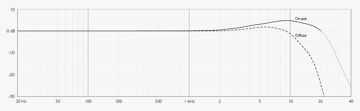
Example: 4006 Omnidirectional Microphone: Frequency Range: On-axis: 10 Hz – 20 kHz. However, the dotted line indicates that the microphone has an output outside the mentioned range.
Ref: IEC 60268-4 Sound System Equipment - Part 4: Microphones (2018)
clause 12.1: Frequency response.
Microphone frequency Range ±2 dB
The effective frequency range is the frequency range in which the microphone does not deviate by more than a specific amount from the ideal/tailored response curve.
The perfect frequency response is not necessarily flat. Some microphones may have tailored frequency responses, for instance, for better intelligibility. The Effective Frequency Range expresses this tailored and intended frequency within a narrow tolerance, i.e. ±2 dB. The specification may show a limited frequency response, however, within narrow tolerances to provide the exact desired precision.
Multiple microphone frequency response curves
Manufacturers of professional microphones may provide more than one frequency response curve, as it is a way to present how the microphone responds to sound coming from different directions and in different acoustic sound fields.
On-axis response
The on-axis response shows the microphone's response to sound incident directly at its diaphragm. The angle of incidence is 0°, and is measured in a free, undisturbed sound field. The measuring distance may influence the frequency response of directional microphones due to the proximity effect. Hence, it should always be stated at which distance directional microphones (gradient microphones) are measured.
Omnidirectional microphones do not exhibit the proximity effect, and thus, the measuring distance is of less importance.
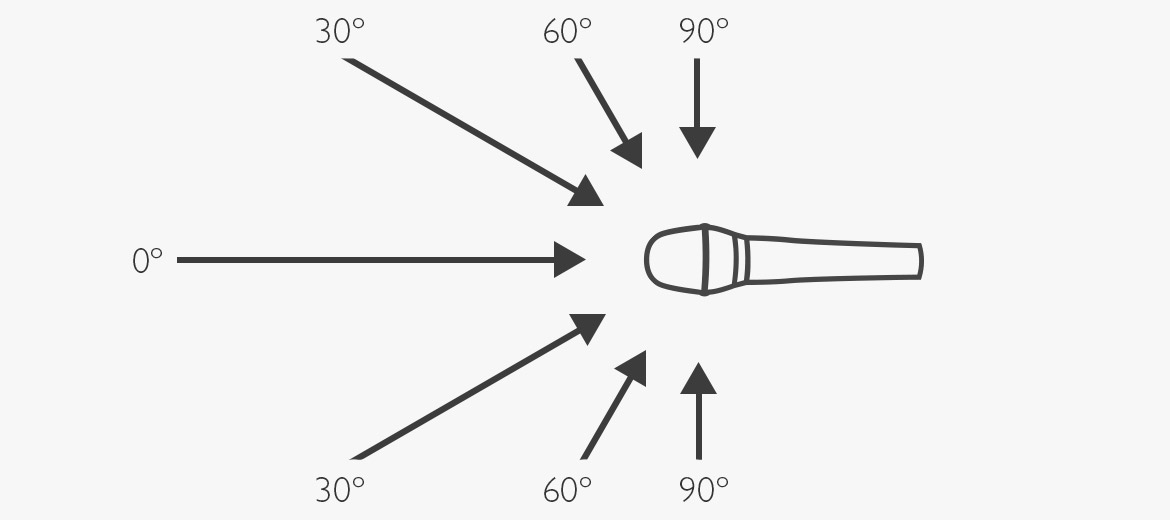
Off-axis responses
The off-axis response shows how the microphone responds to sound arriving from different angles. This is particularly interesting when you want to understand how a directional (i.e., cardioid) microphone suppresses off-axis sound. Even though the off-axis response of directional microphones indicates reduced output, it is crucial that these curves also exhibit a smooth frequency response. Otherwise, off-axis coloration (curtain effect) is introduced.
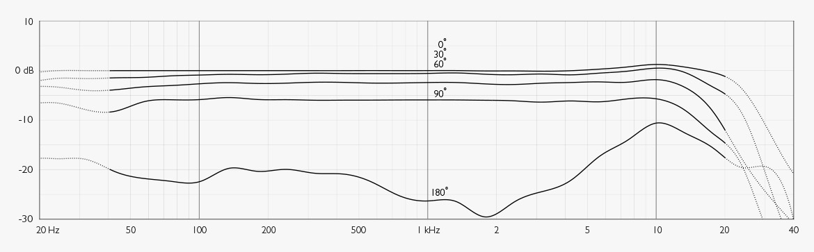
Example: 4011 Cardioid Microphone, On- and off-axis frequency responses. The on-axis response (0°) is measured at 30 cm. The off-axis curves are measured in the far field with the on-axis response as a reference.
Diffuse field response
The diffuse-field response curve illustrates how an omnidirectional microphone responds in a highly reverberant sound field. A diffuse sound field exists in an acoustic environment where sound has no specific direction; all directions are equally probable. The reflections from walls, floor, ceiling, etc., are as loud as or louder than the direct sound, providing equal sound pressure levels everywhere. The diffuse-field response will exhibit roll-off at higher frequencies. This phenomenon is partly due to the air's high-frequency absorption. However, also because there is no high-frequency pressure build-up from the sides and further because the microphone housing may shadow for high-frequency sound coming from the rear.
Ref: IEC 60268 Sound System Equipment - Part 4: Microphones (2018)
clause 12.2: Effective frequency range
Microphone sensitivity (Free-Field Sensitivity)
Sensitivity is the microphone's ability to convert sound pressure into an electrical voltage.
Microphone sensitivity is one of the most important parameters, as it indicates the output voltage the microphone produces in response to a specified sound pressure.
The free-field sensitivity states the voltage a microphone generates when placed in a free sound field at a sound pressure of 1 Pascal (which is the same as a sound pressure level (SPL) of 94 dB).
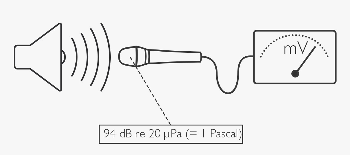
The free field is an undisturbed sound field where the sound has only one direction; this contrasts with a diffuse field, where the sound has all directions. The free-field sensitivity is measured on-axis.
The sensitivity is stated like this: xx mV per Pascal @ 1 kHz or yy dBV/Pascal @ 1 kHz. This is just two ways of saying the same thing.
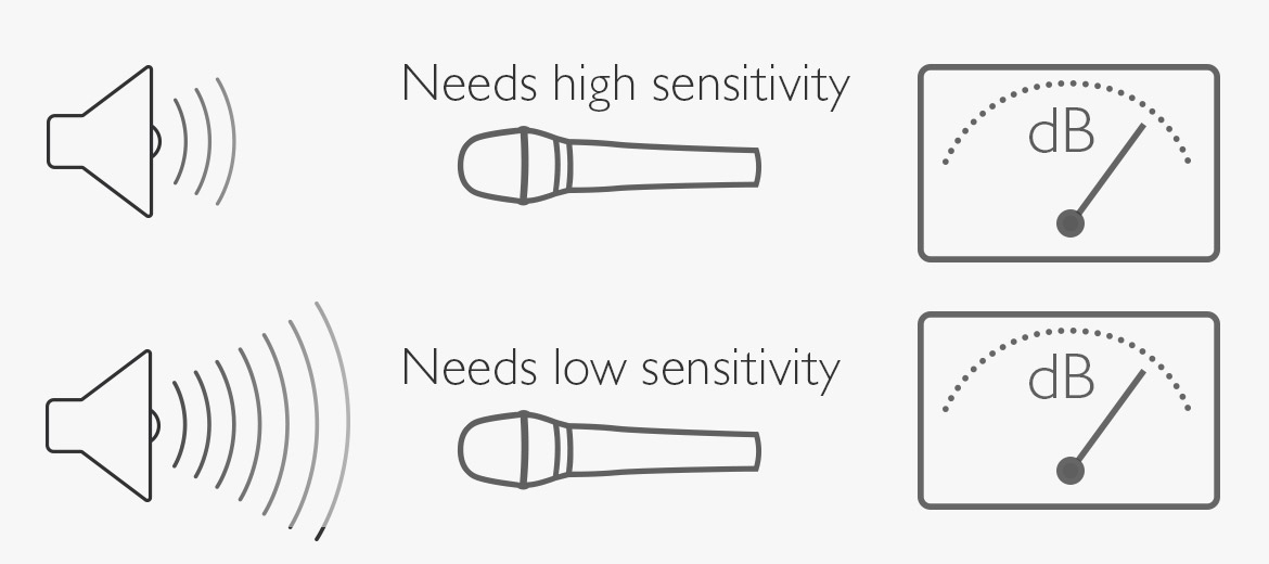
A microphone with high sensitivity produces a high-voltage output and thus requires less amplification (gain) than a microphone with lower sensitivity. In applications with low sound pressure levels, a microphone with high sensitivity is required to keep the amplification noise low. In applications with extremely high SPL, a low-sensitivity microphone is appropriate.
Stated sensitivity is nominal, meaning deviations from this value are expected. For this reason, it is essential to state the tolerances. DPA, in general, specifies the sensitivity within ±2 dB or ±3 dB depending on the microphone type.
Example: 2011 Twin Diaphragm Cardioid Microphone, free-field sensitivity, nominal, ±2 dB: 10 mV/Pa; -40 dB re. 1 V/Pa. Thus, the microphone sensitivity is within 7.9 mV and 12.6 mV when exposed to a 94 dB SPL.
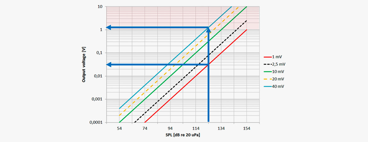
Example: The curves show the output of microphones as a function of the input at different SPL. The lower red curve shows the output of a microphone with a sensitivity of 1 mV/Pa, whereas the upper blue curve shows the output of a 40 mV/Pa microphone. Placing the microphones in an SPL of 124 dB yield outputs of approximately 31 mV and 1.3 V, respectively!
Ref: IEC 60268-4 Sound System Equipment - Part 4: Microphones (2018)
clause 11.2.1 Free-field sensitivity.
Equivalent noise level
The equivalent noise specifies the microphone's self-noise either as an A-weighted RMS level or as an ITU-weighted peak level.
The equivalent noise level (also known as the microphone's self-noise) indicates the SPL at which the microphone produces the same output magnitude as its electrical self-noise. All microphones generate noise due to the (Brownian) movement of the air molecules, which affects the diaphragm and results in an electrical signal. In addition, the electrical circuitry of microphones makes them noisy.
A low noise level is especially desirable when working with low sound pressure levels, so the sound will not "drown" in noise from the microphone itself. The self-noise also dictates the lower limit in the microphone's dynamic range.
There are two common ways to specify the noise:
- The A-weighted RMS-measure approximates the ear's sensitivity, filtering out low-frequency noise. A good result (extremely low noise) on this scale is usually below 15 dB(A).
- The ITU-R BS.468-4 standard uses a different weighting and quasi-peak detection, so on this scale, a good result is below 25-30 dB. This measure is useful for comparing noise in condenser microphones, as it indicates whether the microphone exhibits “popcorn noise” or other forms of crackling.
There is a link between the size of a microphone’s membrane and its ability to be quiet (i.e., exhibit low noise figures). Typically, a larger diaphragm will lead to lower self-noise. This physical fact is why the 4060 Miniature Omnidirectional Microphone, which has extremely low self-noise when compared to similar-sized microphones, still measures an equivalent noise level of 23 dB(A) re 20 µPa. Here is an example of a large membrane microphone:
4041-SP Omnidirectional Solid State Microphone
Equivalent noise level A-weighted: Max. 7 dB(A) re. 20 µPa.
Equivalent noise level, ITU-R BS.468-4 Max. 20 dB
Ref: IEC 60268-4 Sound System Equipment - Part 4: Microphones
clause 16: Equivalent sound pressure level due to inherent noise.
Distortion, THD <1%
Specifies the max SPL (RMS and peak) below which the total harmonic distortion is less than 1%.
A significant component of the microphone is the diaphragm. If the transducer is a condenser type, the diaphragm is positioned in front of the backplate. The space between the two is in the range of 20-50 µm. When placing the microphone in a high-SPL situation, it is evident that there is a limit to diaphragm excursion, at least when pushed in the direction of the backplate. Similarly, the diaphragm material itself has a limit to how "stretchable" it is in either direction. These limitations cause amplitude non-linearity, also called distortion.
Furthermore, the charged backplate attracts the diaphragm (only in one direction), which can also account for non-linear behavior.
Besides the diaphragm and the backplate, a condenser microphone needs an electronic interstage that converts the high impedance of the transducer into a relatively low impedance to feed longer cable-runs. The electronic design may be a source of asymmetric behavior and distortion. (However, CORE by DPA and CORE+ are technologies successfully attempting to improve on this).
Although manufacturers are continuously trying to improve microphones, there always exist limits to microphone systems that eventually may cause distortion.
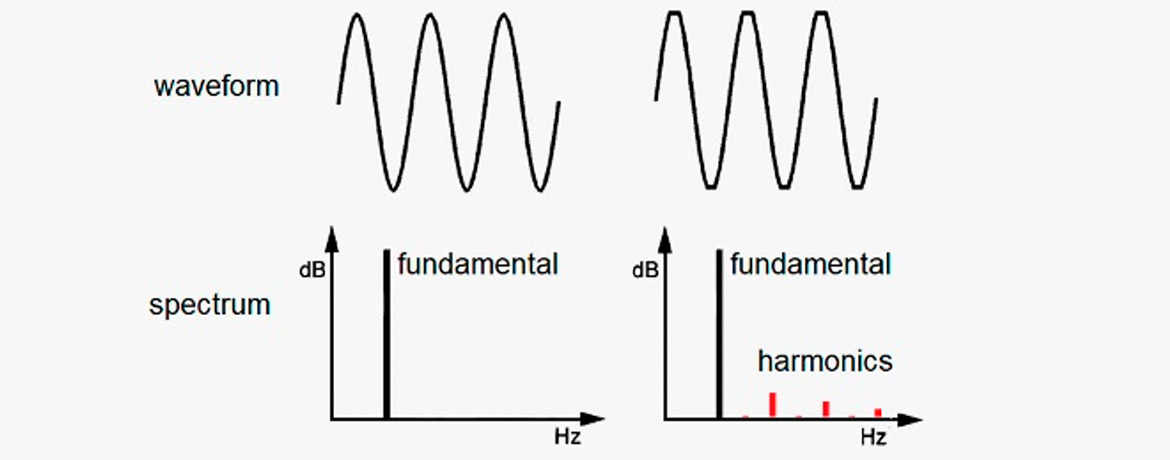
One form of distortion is clipping. When the waveform changes shape from pure sine to some degree of flattop curve (time-domain), harmonics occur in the spectrum (frequency domain). It is the amount of these unintended frequency components, the Harmonic Distortion, expressed as a percentage of the input signal.
At DPA, we specify the SPL up to THD <1%. This value is worth knowing as it forms the basis for calculating the dynamic range of a microphone. Dynamic range is the difference between the RMS-level at which a THD of 1% occur, and the noise floor (self-noise of the microphone, RMS, A-weighted). In addition, the related peak-level is measured and stated in the specifications.
DPA measures the THD at one frequency. The chosen frequency depends on the microphone type (omnidirectional or directional).
Why is THD only measured at one single frequency? Due to practicalities. It is difficult to produce a sound source that can deliver an SPL of (for example) 160 dB with zero distortion, especially if this source should cover the whole frequency range.
At DPA, omnidirectional mics are measured by applying a B&K 4221 High-Pressure Microphone Calibrator. Directional mics are measured using a unique acoustic tube designed by DPA.
When comparing microphones from assorted brands, ensure the THD measurement includes the complete microphone (capsule + preamplifier), as many manufacturers specify THD only for the preamplifier. Typically, the preamplifier distorts much less than the capsule; thus, defining a more extensive dynamic range than is available.
At low levels, distortion should always be below 1%. Increasing the SPL increases distortion. Therefore, what is specified is the max SPL (RMS and peak) at which the THD does not exceed 1%.
Ref: IEC 60268-4 Sound System Equipment - Part 4: Microphones
clause 14.2: Total harmonic distortion.
Microphone max SPL, THD 10%
Specifies the microphone’s response to extreme sound pressures.
This parameter is also called “Overload SPL.” In many recording situations, it is practical to know the maximum Sound Pressure Level (SPL) a microphone can handle and what output voltage to expect in that situation. Please note that in most music recordings, maximum peak SPL easily supersedes the RMS value by more than 20 dB. The RMS value indicates a kind of average SPL, not the true peak level.
For general specifications, the SPL at which a THD of 0.5% or 1% occur is useful, because this is the point at which you start to detect audible distortion.
In general, the distortion of a circular diaphragm will double with a 6 dB increase of the input level, so you can estimate other levels of THD by using this factor.
However, DPA specifies the microphones' maximum peak-SPL. The definition of the max peak-SPL is when the output reaches a THD of 10%. The measurement is conducted at one single frequency, including both capsule and preamp.
Presenting this specification indicates that the microphone delivers increased signal also after the 1% THD is passed. In addition, this specification provides a useful max value for the input section of wireless systems.
(Note: In some brands’ specifications, the max SPL indicates the maximum sound pressure level at which the microphone does not break up! This measure is of no practical use unless you are in the spacecraft business.)
Ref: IEC 60268-4 Sound System Equipment - Part 4: Microphones
clause 15.2: Overload sound pressure.
Rated impedance
Specifies the output impedance, as stated by the manufacturer.
The output impedance of a professional microphone should be low relative to the preamp's input impedance, typically 10 times lower.
The output impedance of condenser microphones is basically determined by resistors. Thus, the impedance is constant with frequency. (In dynamic microphones the coil/magnet/suspension has an influence on the output impedance and results in a less constant impedance with frequency.) In some cases, the nonlinear impedance may affect the frequency response of the microphone. The reason for calling this specification “rated impedance” is that the manufacturer is allowed to call it what he finds best to describe the overall impedance value.
The impedances of DPA microphones are constant with frequency.
Ref: IEC 60268-4 Sound System Equipment - Part 4: Microphones
clause 10.2: Rated impedance.
Minimum load impedance
The minimum input impedance of the external preamp.
A complete condenser microphone has a capsule and an internal preamplifier. When connecting to the outer world, an external preamplifier is applied. The microphone should deliver sufficient voltage to the input of this external preamplifier. However, if the load is too heavy (i.e., too low input impedance), there is a risk of reducing the microphone’s output signal.
Thus, it is practical to determine the minimum load impedance that allows no signal loss.
(Somebody may – for emergency reasons only of course – do a passive split from one microphone into two inputs. If that is the case, the load impedance is less than the lower of the two input impedances!)
Ref: IEC 60268-4 Sound System Equipment - Part 4: Microphones
clause 10.3: Rated minimum permitted load impedance.
Cable drive capability
Long cables may degrade a signal. The loss typically sets in at higher frequencies first (the cable may function as a low-pass filter). To avoid this situation, DPA specifies the maximum cable run without significant loss.
A typical value for DPA microphones is 100 m (328 ft).
This information is not required by any standard.
Output balance principle
Microphone signals are typically 100 times weaker than line-level signals. However, we connect microphones using long cables. So, to minimize the noise induced into the microphone cables, it is crucial to use balanced lines.
In most microphone types (or rather in most microphone’s output amplifiers), DPA uses a principle called “Active Drive.” The Active Drive has balanced impedance (the same impedance to ground from both pin 2 and 3. In this way, the effect of induced electrical noise is massively reduced. (See CMRR).
Whereas the impedance is balanced, this is not the case with the signal. The signal runs only on pin 2. Pin 3 is silent. The advantage of this is a simple and clean circuit that delivers sufficiently high output.
Ref: IEC 60268-4 Sound System Equipment - Part 4: Microphones
clause 16.1: Balance of the microphone output.
CMRR
CMRR stands for Common Mode Rejection Ratio (also interpreted as Common Mode Range Rejection). This measure indicates the efficiency of the impedance balancing. It is a measure of the microphone’s ability to suppress electrical noise, which may be collected predominantly by the wires connecting the microphone to the preamp.
The CMRR is measured in the frequency range of 50 Hz to 20 kHz.
Specs not found
There are more specs than the above mentioned. At DPA, we evaluate microphones on many other parameters: wind, pop, humidity, EMC, vibration, to mention a few. They are not listed at this point. However, in the future, you may find more lines in the spec sheet. DPA wishes to deliver as much useful information to our users as possible.
What you cannot determine from specifications
While microphone specifications indicate a microphone's electro-acoustic performance, they cannot give you the total appreciation of how the mic will sound. Specifications can detail objective information but cannot convey any subjective sonic experience. For example, a frequency response curve can show you how faithfully the microphone will reproduce the incoming pure sinusoidal frequencies, but not how detailed, well dissolved or transparent the result will be.
Conclusion
Microphone specifications do not tell the whole story about a microphone's quality. There is no substitute for the sonic experience. Although microphone specifications may not be fully comparable between manufacturers, when properly evaluated, they do provide useful objectivity and will help in the search for the correct microphone.