Numbers in audio
Even though we work with audio and our primary assessment tools are the ears and the heart, sometimes we need to use numbers to describe sound. Most specifications are based on numbers. When we record, we use numbers to describe the amount of data. If we want to communicate a sound pressure level, we use numbers. And it does not end here.
Decade vs. octave
When describing the attenuating, or gaining slope, of a filter in audio, it is common to define it by “dB per octave” like 6 dB per octave or, in short form, 6 dB/oct.
However, in other fields within electronics, we describe the slope per decade, like 20 dB per decade.
An octave is defined as a doubling or a halving of a value of frequency. A decade is defined ten times (or a tenth of) any quantity (or frequency range); this means the values are not fixed, but relative. The frequency range of the human ear is approximately ten octaves or three decades from 20 Hz to 20000 Hz.
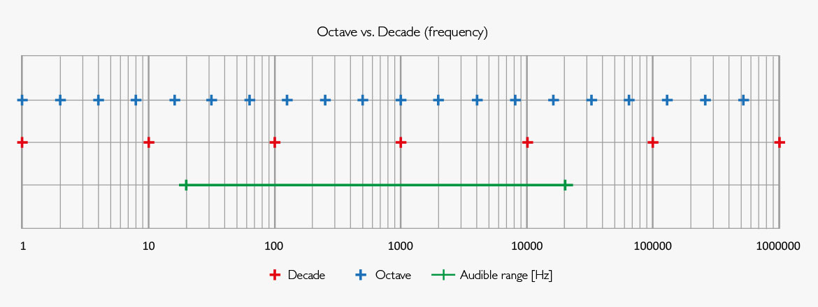
Fig 1 Number line marked with octave and decade intervals.
The order of a filter defines the slope outside their passband. A first-order filter, in principle, contains one electronic component which has a frequency-dependent resistance. This component is usually a coil or a capacitor in connection with a resistor. The slope is ±6 dB per octave depending on the configuration of the two components. A second-order filter includes two of these components in combination with a resistor, like two capacitors or one coil and one capacitor: The slope obtained then is ±12 dB per octave. Today these filters are typically only found in passive loudspeakers, whereas most filters are made digitally via DSP power.

The table below shows filter order and the affiliated slopes (here attenuation) defined by dB/oct or dB/decade.
| Filter order | 1 | 2 | 3 | 4 | 5 | 6 | 7 | 8 | 9 | 10 | |
| dB/octave | 3 | 6 | 12 | 18 | 24 | 30 | 36 | 42 | 48 | 54 | 60 |
| dB/decade | 10 | 20 | 40 | 60 | 80 | 100 | 120 | 140 | 160 | 180 | 200 |
Conversion table: Filter slopes defined by filter order, dB/oct or dB/decade.
Linear and log scales
There is a fixed interval between each unit of the linear scale (e.g., 1, 2, 3, 4, where the distance between each unit is 1).
The logarithmic scale has a fixed ratio between each unit of the scale (e.g., ratio 10, the units are: 1-10-100-1000, etc. - or ratio 2, the units are: 1-2-4-8-16, etc.) This logarithmic scaling applies to many electrical or acoustic measures, which specify microphones (i.e., Volt, Pascal, etc.).
Humans perceive both level and frequency in a logarithmic manner. Regarding frequency, we read the frequency response curve using a logarithmic scale. The decibel scale is related to the way humans perceive level. Thus, the scale is logarithmic, which provides the perception of equal-sized increment.
The decibel (dB)
The advantage of this scale is that 1 dB is about the minor change of level you can hear. 3 dB is an evident audible change. 10 dB is subjectively perceived as a doubling or a halving. By and large, each step on the scale is perceived as equal in size. The most significant dB-number you will find in real life is <200 dB, meaning, if the dB number has three digits, the first always being “1”.
The dB scale is relative. Thus, you can express any change by dB. A change of 0 dB is no change at all. Any positive dB number indicates a positive change (the value is higher than before). Any negative dB number indicates a negative change (the value is lower than before).
You can make dB an absolute scale by applying a reference — for instance, the sound pressure level, the reference being 20 μPa. Now 0 dB means that sound pressure is present, and it is 20 μPa (approximately the threshold of hearing at mid-frequencies). Describing the level of sound pressure, “dB re 20 μPa” also can be written as “dB SPL” (Sound Pressure Level).
For electrical measurements, another reference is 1 Volt, written as “0 dBV” or “0 dB re 1 Volt”. This absolute value applies, for instance, to the specification of microphones’ sensitivity.
Bandwidth and percentage vs. Q
Parametric equalizers typically include bell-shaped filter responses, bandpass/stop filters. The control parameters provided are frequency, level, and Q-factor or bandwidth. In filters defined for measurement techniques, also a percentage may apply to describe the bandwidth. Bandwidth, Q-factor, and percentage express the same thing. However, it depends on the filter brand, model and application which parameters that apply. On some devices though, you can switch between them.
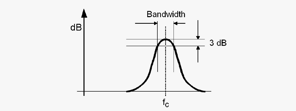
Here are the relations between the different terms:
Bandwidth
Bandwidth is the frequency span between the -3 dB cutoff points on a response curve, i.e., fupper - flower [Hz]. The bandwidth is expressed either in absolute value [Hz] or relative in octaves (often in 1/1 octave, 1/3 octave or fractions of an octave expressed by decimal numbers, for example, 0.1 octaves).
Percentage
The bandwidth expressed as a percentage:

where
fu = upper cutoff frequency [Hz]
fl = lower cutoff
fc = center frequency [Hz]
Example: (1/1 octave ~ 70%, 1/3 octave ~ 22%).
Q-factor
A filter’s Q factor is calculated like this:

where
fres = resonance/center frequency [Hz]
b = bandwidth [Hz]
Prefix in numbers
A prefix is an affix placed before a word or a number to modify its meaning. A numeral prefix is practical as it makes it easier to understand extremely small – or extremely large – numbers.
A prefix replaces the power notation. For instance, “2000” equals “2 times 10 to the power 3” or written as “2*103”. Notated by prefix: “2k” as “k” indicates a factor of 1000.
Here is a list of numeral prefixes as defined by the SI-system:
| Prefix | Abbreviation | Power | Value |
| Tera | T | 1012 | 1 000 000 000 000 |
| Giga | G | 109 | 1 000 000 000 |
| Mega | M | 106 | 1 000 000 |
| kilo | k | 103 | 1 000 |
| hecto | h | 102 | 100 |
| deka | da | 101 | 10 |
| base unit | - | 1 | 1 |
| deci | d | 10-1 | 0.1 |
| centi | c | 10-2 | 0.01 |
| milli | m | 10-3 | 0.001 |
| micro | µ | 10-6 | 0.000 001 |
| nano | n | 10-9 | 0.000 000 001 |
| pico | p | 10-12 | 0.000 000 000 001 |
The unit for the capacitance of a capacitor is Farad. However, often the physical capacitors exhibit values that are a small fraction of the base unit; for instance, 0.0000000000022 Farad. This is more easily written as 2.2 pF (pico Farad).
Or a resistor may have a value of “1000000 Ω, more easily notated as “1 MΩ”.
Or a microphone has a sensitivity of 0.01 V, more easily noted as “10 mV”.
When we talk about the barometric pressure in air, we are in the range of 1000 hPa (hecto Pascal). and not 100 kPa, which would be more straightforward. However, here the former tradition of using Bar instead of Pascal shines through because 1000 milliBar = 1000 hPa.
Confusion between general numbering and quantification of computer data.
When calculating the size of any digital information handled by computers, one must be aware that it is all based on bytes [B], which each contain 8 bits. Thus, the number of bits per sample is calculated as an integer multiplied by the number 8 (1 ´ 8, 2 ´ 8, 3 ´ 8, and so on). The number of bits per sample of linear PCM is either 8 (1 byte), 16 (2 bytes), 24 (3 bytes), or 32 (4 bytes). For higher resolution and internal processing, 64 bits or more may apply.
Because these numbers get large, the use of prefixes is useful. The prefix units are defined in the SI system, which uses “k” (kilo), “M” (Mega), “G” (Giga), “T” (Tera), and so on. However, while using the same prefix names, it is the binary definition we apply as soon as we describe file sizes, which is rather confusing!
Here is how to calculate file sizes as they appear on your computer:
1 B = 8 bits
1 kB = 1024 B = 8192 bits
1 MB = 1024 kB = 8,388,608 bits (≈ 8.39 ´ 106 bits)
1 GB = 1024 MB ≈ 8.59 ´ 109 bits
1 TB = 1024 GB ≈ 8.8 ´ 1012 bits
Example:
How much storage capacity is needed for a 1-hour stereo recording in 44.1 kHz/16 bit?
The total number of bits is calculated as follows:
Sampling frequency x no. of bits per sample ´ no. of audio channels ´ the duration of the recording (in seconds):
[1 hour = (60 min. ´ 60 seconds) = 3600 seconds]
44,100 (samples per second) ´ 16 (bits per sample) ´ 2 (channels) ´ 3600 (seconds) = 5.08 109 bits
Number of bytes: 5.08 ´ 109 / 8 = 6.35 ´ 108 B
Number of kB: 6.35 ´ 108 / 1024 = 6.20 ´ 105 kB
Number of MB: 6.20 ´ 105 / 1024 = 605.6 MB
Prefixes for binary-based numbers have existed for many years. Some manufacturers use binary prefixes when specifying their hard drives. Here is a table that compares the decimal prefixes to the binary prefixes, as defined by the IEC (International Electrotechnical Commission) or the JEDEC (Joint Electron Device Engineering Council).
| Decimal | Binary | ||||||||
| Value | SI | Value | IEC | JEDEC | |||||
| factor | symbol | name | factor | symbol | name | symbol | name | ||
| 1000 | 103 | k | kilo | 1024 | 210 | Ki | kibi | K | kilo |
| 10002 | 106 | M | mega | 10242 | 220 | Mi | mebi | M | mega |
| 10003 | 109 | G | giga | 10243 | 230 | Gi | gibi | G | giga |
| 10004 | 1012 | T | tera | 10244 | 240 | Ti | tebi | - | - |
| 10005 | 1015 | P | peta | 10245 | 250 | Pi | pebi | - | - |
| 10006 | 1018 | E | exa | 10246 | 260 | Ei | exbi | - | - |
| 10007 | 1021 | Z | zetta | 10247 | 270 | Zi | zebi | - | - |
| 10008 | 1024 | Y | yotta | 10248 | 280 | Yi | yobi | - | - |
Table
In this table, decimal-based prefixes are compared to binary-based prefixes.
Unfortunately, it is most common to use decimal prefixes like they were binary.
In the example mentioned above, the correct calculation yields this result: 605.6 MiB.
Note also that the Ki uses capital letter K. Sometimes, you may see K (without the “i”) also meaning Ki.
IEC 60027-2, Second edition, 2000-11: Letter symbols to be used in electrical technology - Part 2: Telecommunications and electronics.
