A guide to pro wireless audio - Part 6: Antennas, cables, combiners and splitters

6.01 Antennas
Antenna selection and handling are crucial to the performance of wireless systems.
An antenna must be at least 1/10 of the actual wavelength to be effective. However, it only becomes truly effective when (depending on the principle) it has a size slightly below - approximately 0.9-0.94 times - a quarter or half of the wavelength.
The electromagnetic field of the transmitting antenna has an electric component and a magnetic component. The electric component is oriented similarly to the antenna, while the magnetic component is oriented perpendicular to the antenna. For optimal transmission of the direct field (a field without reflections), the transmitter and receiver antennas must be oriented in the same way. In a field with many reflections, this orientation is not so crucial. When using the UHF bands indoors, it is therefore not decisive whether the receiving antennas have the same orientation or point directly toward the transmitter because, in most cases, it is a reflected field that is received. Outdoors (in a direct field without reflections), the difference is only 3 dB at 90 degrees.
 Figure 6.01. Antenna current and voltage depend on wavelength.
6.02 Antenna impedance
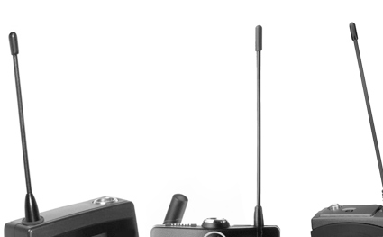
Antennas, depending on whether they are full-wave, half-wave or quarter-wave, have a characteristic impedance at the frequencies they are tuned to. The output stage of the transmitter and the transmitting antenna must match each other for optimal power dissipation. Suppose the antenna does not have the correct length for the frequency in question (typically, it is too short). In that case, it may be necessary to compensate for the mismatch by, for example, inserting a coil in series with the antenna. This approach is particularly useful for wireless handheld microphones, where an antenna of optimal length can easily be impractically long (see later).
External antennas for wireless systems usually strive to obtain an impedance of 50 Ω.
6.03 Dipole, half-wave antenna
A half-wave antenna designed as a dipole ideally has a characteristic impedance (radiation resistance) of 73.6 Ω at the feed point of the resonant frequency. However, as with other antennas, the actual impedance will differ, typically being higher, due to the influence of connectors, cables, mounting, etc.
The thickness of the antenna itself is also essential. The thicker the antenna, the more broadband (covering a broader frequency range).
6.04 Folded dipole, half-wave antenna
A half-wave antenna, shaped like a folded dipole, has a characteristic impedance of approximately 300 Ω. A transformer is typically connected between it and the asymmetrical cable if this is used. A transformer with a conversion ratio of 2:1 is used, which gives an impedance conversion of 4:1. The 300 Ω is then converted to 75 Ω, a typical impedance for connection to the transmitter/receiver.
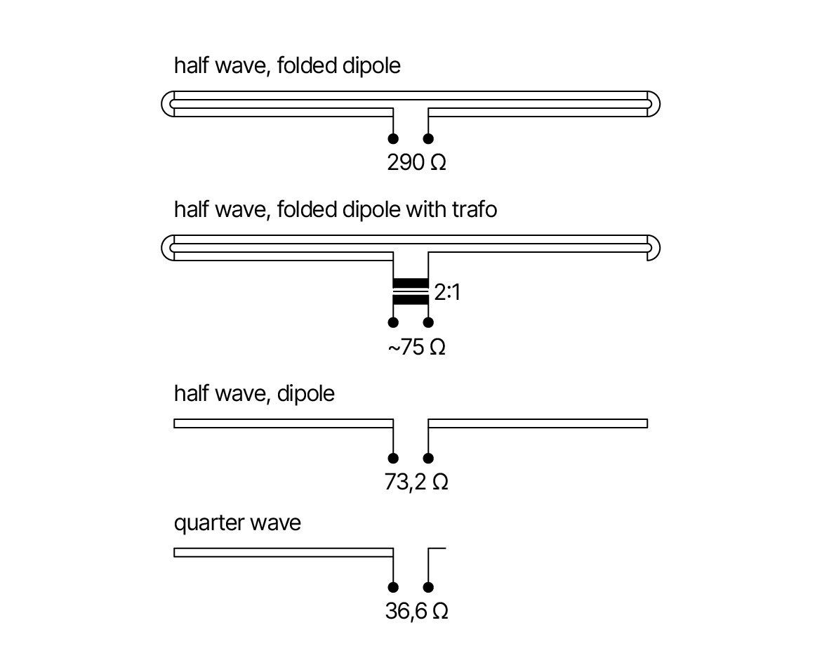 Figure 6.02. Folded dipole, half-wave antenna with transformer.
6.05 Quarter-wave antenna
The quarter-wave antenna is usually designed as a semi-dipole, i.e., with one end referring to the ground plane. For example, it can be a true ground-plane antenna with one vertical element (the antenna itself) and three inclined elements (the ground plane). The ground plane can also be made up of metallic surfaces. This is usually the case with the telescopic antennas that come with some receivers. Here it is the receiver itself that more or less forms a ground plane.
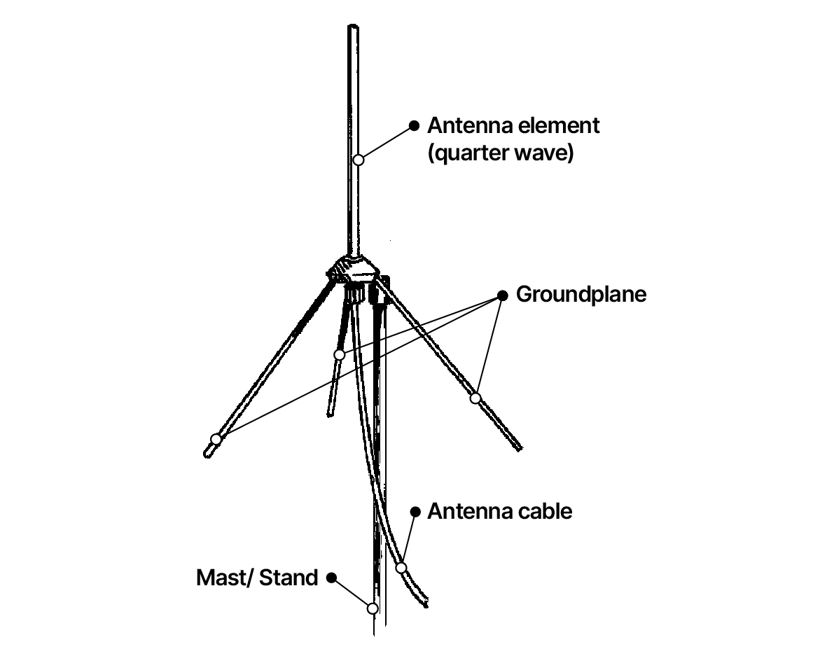 Figure 6.06. Ground plane antenna.
6.06 Coil for impedance matching
As mentioned earlier, it may be necessary to add a coil to an antenna that is too short in order to achieve a suitable impedance and, thus, optimal power handling.
Coil antennas are usually critical in terms of frequency tuning. Therefore, these antennas should always be ordered according to the specific frequency they are to be used for.
Proper mounting on a wireless handheld microphone, for example, is also critical. If the mounting is not correct, sidebands, i.e., harmonic frequencies above and below the transmission frequency, can occur, which can cause interference on other channels.
Touching the antenna should be avoided as both it (and the electromagnetic field it generates) are easily damaged by touch.
6.07 Yagi antenna
It may be necessary to use directional antennas, for example, when transmitting/receiving over long distances.
The Yagi antenna is a directional antenna consisting of a folded dipole, a director and a reflector. The distance from dipole to director/reflector is approximately 1/10 of the wavelength. Often there are multiple directors on a Yagi antenna. The gain in the axis direction is approximately 6 dB.
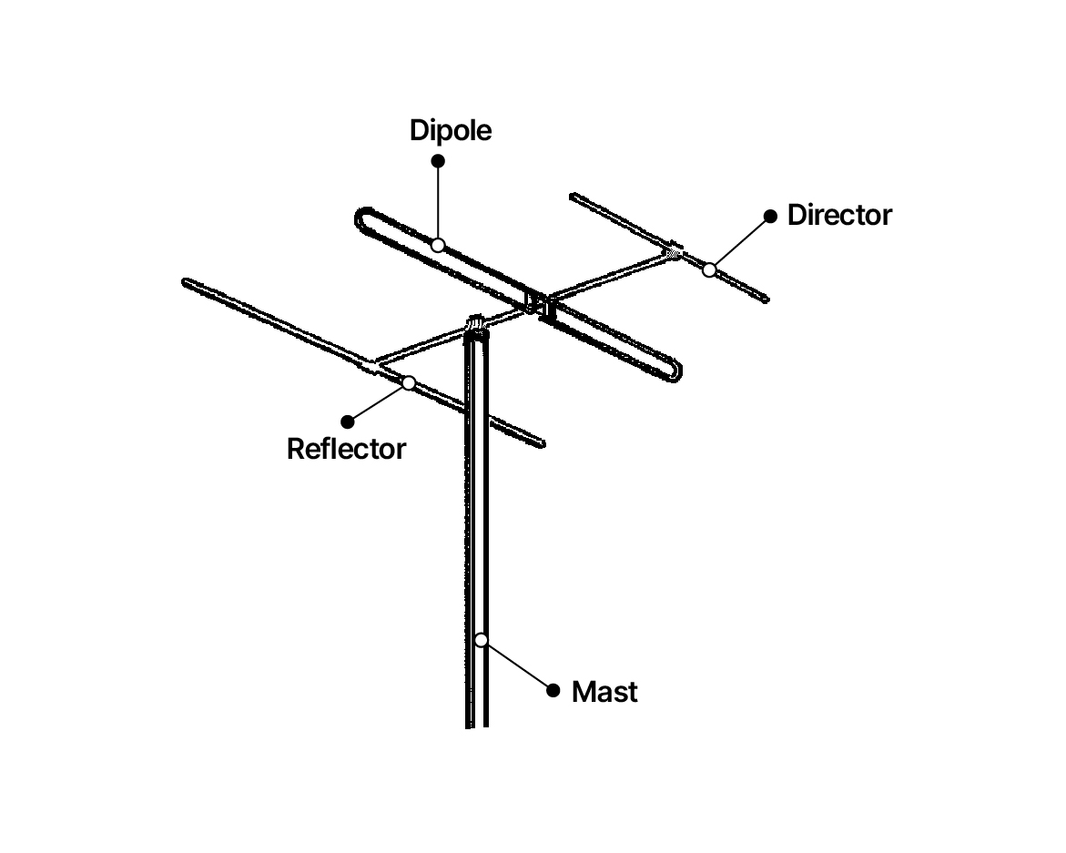 Figure 6.07. Yagi antenna.
6.08 Pflaunder, shark fin and similar antennas
These are also directional antennas. The minimum angle is typically 120-130°, where the sensitivity is approximately 12 dB lower than in the axis direction. At 180°, the sensitivity is typically -10 dB. The antennas can be tuned and used both as a transmitter and receiver antenna.
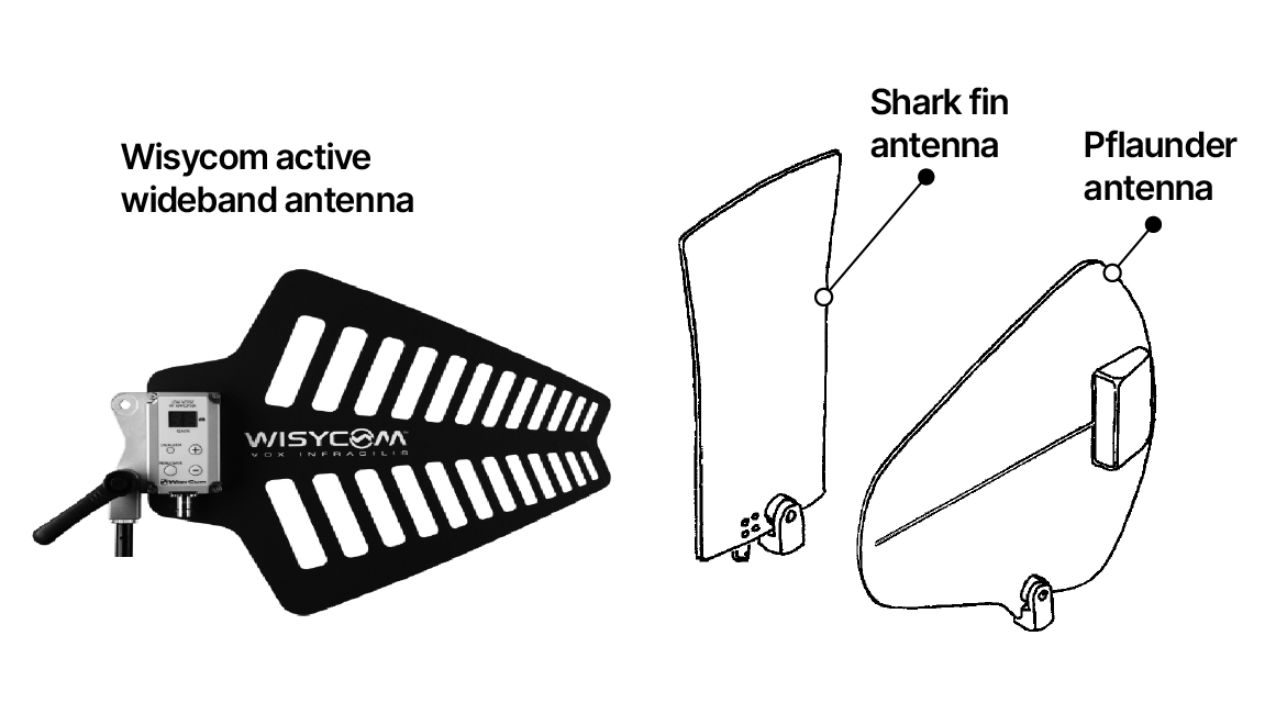 Figure 6.08. Directional antennas: Wisycom Active Wideband, and Shark fin and Pflaunder antennas.
6.09 Tuning of the antenna
Transmitter antennas are usually optimized as much as possible, ensuring that they are tuned to the applicable frequencies.
Receiver antennas are usually designed to behave more broadband so that the signal from the same antenna(s) is distributed to multiple receivers via antenna splitters.
6.10 Antenna placement
In general, receiver antennas should be placed to in direct line of sight of the transmitter antennas and be oriented equally (vertically). However, indoors, this is not really critical.
Diversity antennas should be placed at least 1/4 wavelength apart.
Transmitter antennas and receiver antennas should always be a minimum of 4 meters apart. Similarly, two transmitter antennas should not be placed too close to each other. In all cases, interference will occur, resulting in poor sound, noise and distortion.
Receiver antennas should be mounted to have a clear line of sight to the transmitters. For example, they should be raised above head height if transmitters are used in areas where listeners stand close together. In addition, a set of antennas for diversity reception (and similar) should permanently be mounted in a room so that at least one antenna has good reception conditions close to the transmitter's position. If the receiving antenna is mounted in front of a stage, ensure that the transmitter is usually positioned in front of the actor/speaker, i.e., in a pocket or the like, facing forward.
Ground plane antennas in TV studios and similar locations should not be placed too close to the lighting grid, which is often grounded. If necessary, the antenna can be mounted upside down so that the ground plane of the antenna faces the ceiling.
When mounting antennas on people, try to get a distance of 5 cm from the body. Close mounting can lose 99% of the transmission power due to misalignment. In particular, avoid getting the antenna wet with sweat. The transmitter itself should also be mounted in a waterproof bag. In addition to mismatch, the body itself can shield the field.
Antennas and cables should always be connected as specified, i.e., with the correct connectors, mounting, etc. Otherwise, the system's efficiency will be reduced because the cable can start acting as a (mismatched) antenna.
6.11 Boosters
A booster is an amplification stage for the antenna signal. A booster cannot distinguish whether the signal is noise or the signal from a transmitter. Therefore, there is no benefit to using a booster until it is strictly needed. Boosters are generally only there to compensate for the cable loss and should preferably be left at 0 dB if possible.
In practice, the highest gain needed will be 18 dB.
6.12 Cables
Cables are selected according to impedance and attenuation. The conductor and shield form a condenser that short-circuits the signal to a certain extent. Therefore, thicker cables have the least attenuation, which can be challenging to manage in the field. This can be a reason to avoid longer cables than necessary. It is, therefore, best to place the receiver close to the antenna and route the AF signal in the long wires instead.
Choose a cable with an impedance that matches the antenna and transmitter or receiver for optimal transmission.
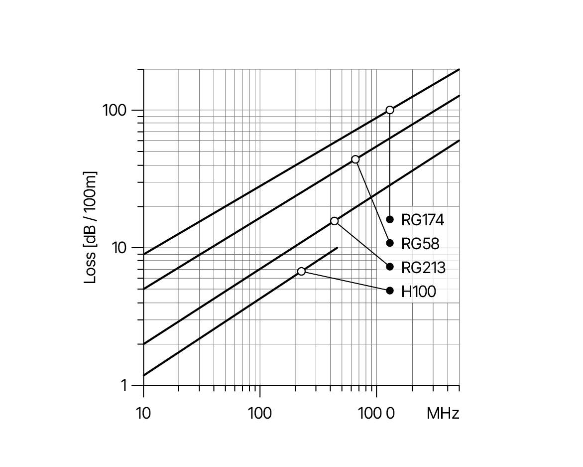 Figure 6.09 Loss in 50-Ω cables per 100 meters.
6.13 Passive splitter
A splitter is a device that can distribute an antenna signal between several receivers, for example. As impedance matching is required, there is always an inevitable loss in the passive splitter, depending on the number of outputs.
The loss is:
1:2 - 4 dB
1:3 - 6 dB
1:4 - 8 dB
1:6 - l0 dB
6.14 Active Splitters
When a higher channel count is required, you typically need an active splitter to preserve the signal without loss, as described above. Several solutions are available, but you need to look at how linear they are, as this is a critical parameter when dealing with RF signals. Each non-linearity leads to distortion, which will corrupt the reception of the RF signals. Furthermore, you must ensure the active splitter covers all the frequencies, accomodated by your receivers. If you have a wireless system that can work outside this frequency, you are losing out on many possible transmission channels.
The same counts for higher-end receivers with built-in antenna cascading possibilities. You need to ensure how many units the manufacturer suggests can be cascade coupled (many only one) and what the signal looks like on the output, as it may have added noise and/or less optimal signal strength. Furthermore, most of these cascade outputs are not wideband but are limited to the narrow-band frequencies that the particular receiver is covering. This means that you cannot mix and match two different band receiver outputs as they do not overlap.
6.15 RF Combiners/matrices
In larger installations, you may need to combine a high number of antennas that are positioned in separate locations. Typical applications could be a production center where a control room has to work with several studios at the same time, or a theater that needs, from time to time, to combine mainstage, foyer or lobby. Also, an ENG or OB-Van facility will benefit from the freedom to manage different RF areas. Here a Combiner/Matrix solution is helpful. The flexibility, along with the possibility to work in wideband, allows for easy deployment of wireless audio infrastructure and also optimizes the overall CAPEX (i.e., sharing resources like wireless microphones).
6.16 RF over Fiber (RFoF)
Distributing antenna signals over larger distances using conventional cables is not optimal. Too much signal might be lost. Instead, the distribution of RF over fiber is designed for this specific purpose. The technology is called Course Wavelength Division Multiplexing (CWDM). An affiliated technology is Dense Wavelength Division Multiplexing (DWDM). Both CWDM and DWDM are technologies used in fiber-optic networks to send multiple signals on different wavelengths of light across a single strand of fiber cable.
6.17 Noise
Several things can cause noise in reception. First, it can be a sign that the received signal is too weak, either because the transmitter and receiver antennas are too far apart, the antennas do not have direct line of sight each other or out-phasing occurs.
If there are “noise tails” on the signal, it usually means that the transmitter is modulated too weakly. Therefore, the LF gain on the transmitter itself must be increased.
Noise can also be caused by electromagnetic radiation in the antenna cable, e.g., long cables running in a cable tray with light cables, past relays or other electrically noisy installations. This is a good reason to avoid long antenna cables. If you do have to run the antenna cable through a noisy environment, you can run the cable in an iron water pipe. Connect one end of the pipe to the ground. There should be no electrical connection between the cable and the pipe.
In today's production environments, a common source of noise is LED screens, LED lighting fixtures, and other transmission gear like automated systems using the same spectrum.