A guide to pro wireless audio - Part 5: Reception

Frequency tuning
The transmitter and receiver must be very stable in terms of transmission frequency tuning. Previously, both devices were crystal-controlled. First, one crystal per frequency, later a single crystal that functioned as a reference for all frequencies as it would have a very low resonance frequency. Physically, this requires a larger crystal, which has the advantage of being more robust to external influences such as heat and shocks. In the specifications, terms such as XO (crystal oscillator), synthesizer tuning, or PLL (Phase Locked Loop) describe the circuits that ensure many transmitter/receiver frequencies. Today, oscillators are generally based on digitally-generated frequencies, which makes them much more immune to temperature changes and physical impacts.
Principles for reception
Several reception principles are used. The methods have gradually become more sophisticated to avoid signal dropouts experienced as uneven reception across the covered area. Elements in the surroundings of the receiving antenna may cause single reflections. Single reflections, unfortunately, can be experienced as drop-outs because the carrier is canceled if the reflected signal is out-of-phase compared to the direct signal.
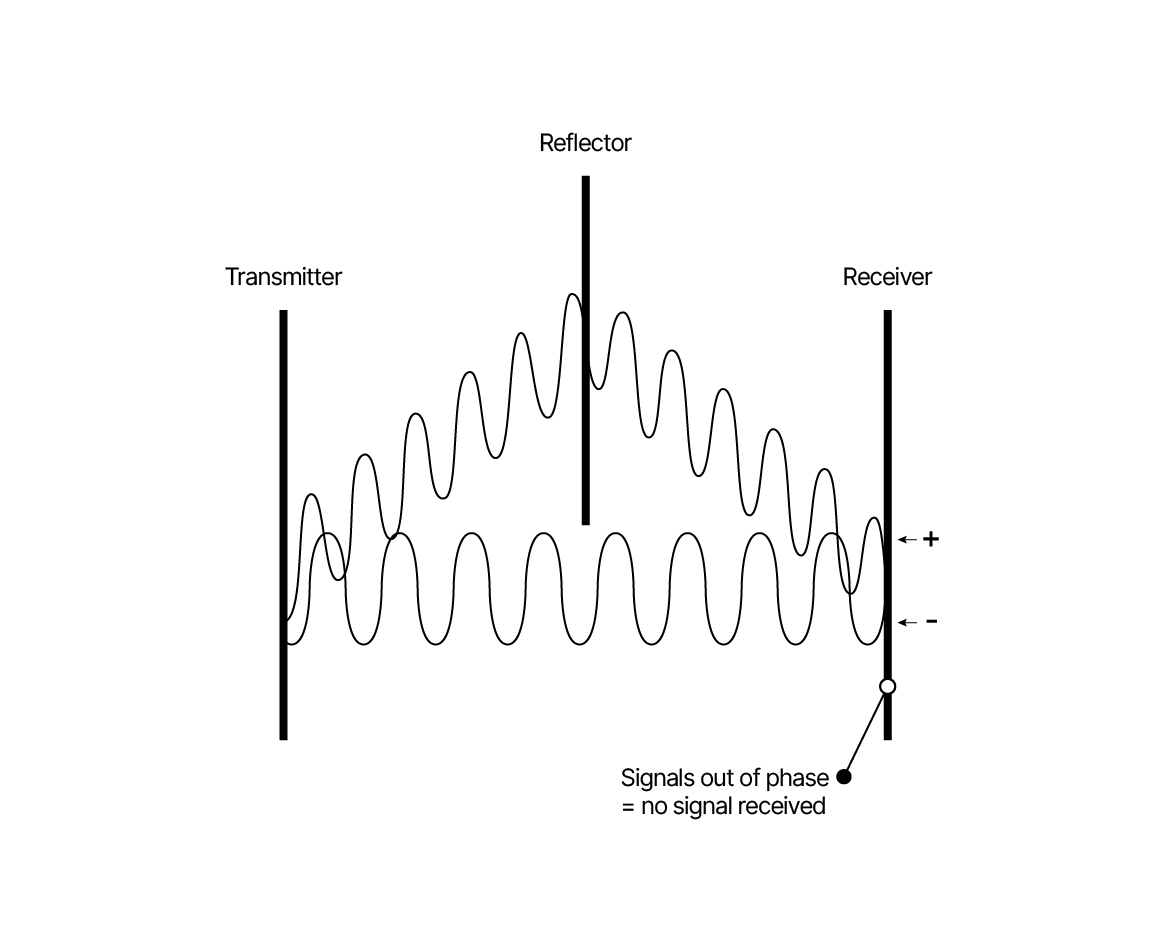 Figure 5.01. Reflections may result in a drop-out of sound.
The most straightforward receiver setup consists of an antenna plus a single receiver. This setup can manage the vast majority of tasks.
In some cases, using two antennas on one receiver is possible. However, this requires that the antennas do not have direct line of sight to each other, or else dropouts are generated. The antennas are connected via an antenna combiner. There will be a loss when using such a passive combiner. With two antennas: 3-4 dB. This setup can work when one transmitter is used in two rooms (one at a time). Historically, systems with three antennas have been used based on the argument that three antennas are less likely to produce a dropout.
Diversity (Receiver Diversity)
A true diversity system utilizes two antennas connecting to two tuners, respectively. The output signals from the demodulator are connected to a comparator, and its output signal is always switched immediately to the better-quality signal. Although the cost of this true diversity receiving mode is higher, it improves signal reception quality and frees it from signal dropout and noise interference.
AAC (Automatic Antenna Control, Antenna Diversity)
AAC also uses two antennas. Here, the antenna signal from two receiving antennas is constantly compared. This happens typically at a speed of 100 times per second.
The advantage is that it is a slightly simpler (cheaper) system than receiver diversity, as only one receiver is needed per channel. However, the audio quality cannot match the receiver diversity. Under some conditions, the switching becomes audible.
 Figure 5.02. Receiver principles.
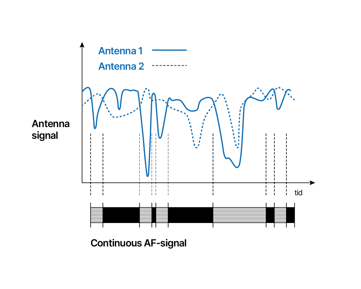 Figure 5.03. Signal variations in the received RF without and with diversity.