A guide to pro wireless audio - Part 4: Digital systems
Pure digital systems
Digital wireless microphone systems take advantage of the fact that a digital signal does not require a high signal-to-noise ratio. This allows for a constant quality for a significantly more variable signal at the receiving antenna than is otherwise possible with pure analog FM modulation. Typically, the signal-to-noise ratio is in the range of 100-125 dB.
Different strategies are used to optimize analog-to-digital conversion to make it simple. A microphone's dynamic range may easily exceed 100 dB. So, the strategy can be either to fit the analog signal to the converter or fit the converter to the analog signal. The first implies an analog level setting to make the signal work inside the dynamic range available in the digital domain. The second takes advantage of cascade coupled converters (stacked converters), so the complete dynamic range of the microphone is covered.
In today’s pure digital transmission systems, most manufacturers utilize stacked converters, meaning the gain on the transmitters does not need to be set, as the dynamic range of these converters outperforms the dynamic range of the attached microphones/sources. However, it can be desirable to adjust the output on the receiver side to compensate for the low signal you can now pass without limitation, but this is a question of level matching/digital trim than gain setting.
Transmission capacity
Unfortunately, there are limits to the amount of data that can be transmitted. The amount of information is mainly determined by the digitized signal's sampling frequency and resolution (number of bits per sample). For instance, if the sampling frequency is 48 kHz and the resolution is 24 bits, the number of bits per second is 48000 * 24, which equals 1,152,000 bps (bits per second). Or 1.1 Mbps (Megabit per second).
Further, some redundancy data is also needed to ensure a stable connection even if drop-outs occur. The total amount of data is in the range of 1.5 times the audio data. So, in this case, the final bitrate is approximately 1.6 Mbps. Unfortunately, modulating this amount of data with the applied technologies is impossible.
Too much data makes the carrier take up much more space compared to standard analog modulation. Another side effect is that the reach of a digital system is reduced if the amount of data is too high.
Bit reduction/CODECs
Bit-reducing algorithms must be applied after the digitization of the audio signal. The typical reduction is in the range of 6:1 – 8:1. Meaning only one-eighth or one-sixth of the original data is transmitted. Usually, the reduction is conducted by applying perceptual coding. Perceptual coding organizes the bits in a way where artifacts are the least audible. MP3 is an example of perceptual-coded audio.
Some brands apply APT-X Live, where 24 bit/48 kHz is transferred at 144 kbps (instead of 1,125 kbps). Other brands have developed proprietary CODECs, like Sennheiser’s SeDAC. (CODEC is a contraction of the terms COding and DECoding).
Most systems encrypt the already digitized AF signal, making it impossible for unauthorized listeners to monitor the communication if the radio waves reach further than intended. This is relevant when wireless microphones are used in corporate or governmental arenas, where confidentiality is important.
The digital signal is restored to its original linear format on the receiving side, typically via a sample rate converter (SRC). Good digital systems can achieve excellent dynamic range, limited distortion, and higher uniformity of the received audio signal.
Latency
Nothing comes for free, and one of the issues with digital systems is that the CODEC (and other applied processing) adds delay to the signal – all digital processing takes time. The best CODECs need at least 2-3 ms (milliseconds) from the microphone input to the receivers’ AF output. Some systems reach a latency of 7-8 ms. To this comes possible latency in the network. For comparison: The latency of pure analog systems is 0 ms.
FM modulation of digital information
The digital information, “zeros” and “ones,” must be modulated onto the RF carrier. Different techniques can be considered.
ASK, Amplitude-Shift Keying will generate a tone representing ”1”, and silence representing ”0”.
Or FSK, Frequency-Shift Keying, where two different frequencies represent”1” and ”0” respectively.
Or PSK, Phase Shift-Keying, where the polarity swops for each transition from ”0” to ”1” or ”1” to ”0”.
The methods are graphically illustrated in the figure below:
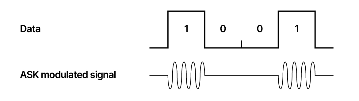 Figure 4.01a Principle of amplitude shift keying (ASK).
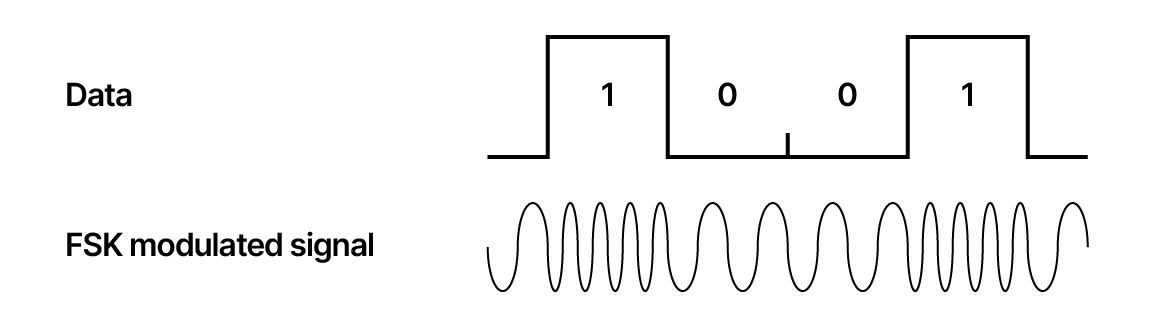 Figure 4.01b Principle of frequency shift keying (FSK).
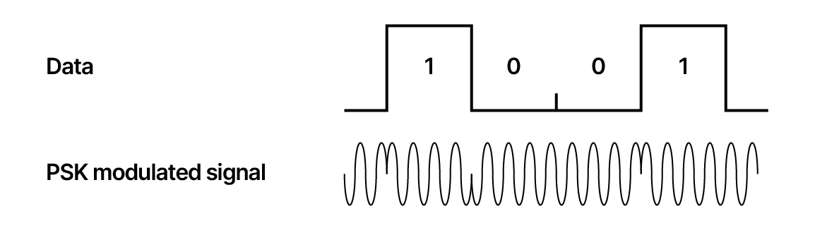
Figure 4.01c Principle of phase moduladet signal (PSK).
Higher order modulation (digital systems)
The systems mentioned above only provide a maximum transmission rate of 150 kbps, which is a limitation. Hence, it is common to apply so-called higher-order modulation, like the QPSK (Quadrature Phase-Shift Keying), which expands the bitrate. See the figure below.
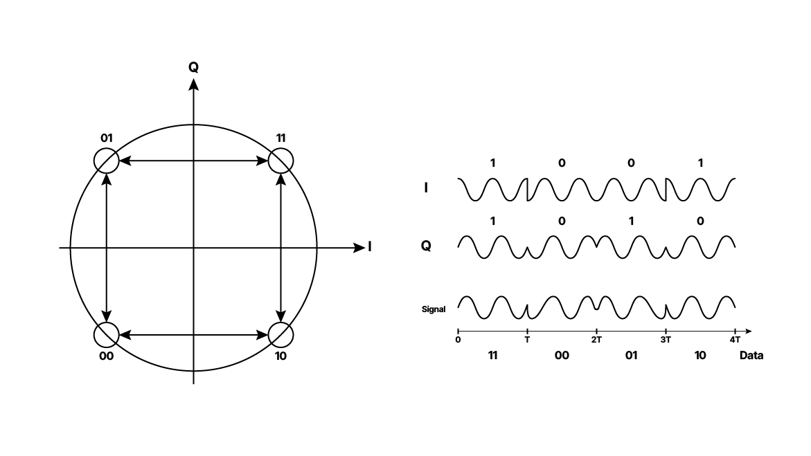 Figure 4.02. Principle for Quadrature Phase-Shift Keying (QPSK). The basic idea is that no value ends at zero. Right: Timing diagram for QPSK. The binary data stream is shown beneath the time axis. The two signal components with their bit assignments are shown at the top, and the total combined signal is at the bottom.
Even more advanced coding can be applied: Differentially encoded binary-, quaternary-, 8-, and 16-phase-shift-keying, DBPSK, DQPSK, D8PSK, and D16PSK, and 8- and 16-quadrature amplitude modulation, D8QAM, and D16QAM – all with the purpose to increase data transfer within the available frequency space per microphone-channel.
Carriers’ bandwidth
The modulation challenge is to prevent the carrier from getting over-modulated and disturbing neighboring channels. In general, digital channels take up more space than analog ones. Below is an illustration that shows the typical difference between the occupied space of an analog and a digital channel.
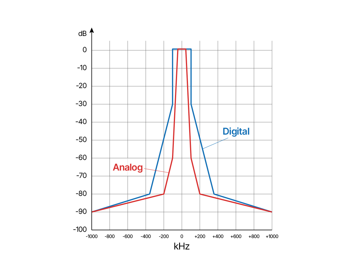 Figure 4.03. Analog and digitally modulated carrier. The digital-modulated carrier typically takes up more space than the analog-modulated carrier.
Narrowband or wideband (digital systems)
The individual transmission frequency can be selected on the transmitter and receiver unit. However, the range of frequencies to choose from may vary. Some brands need several models to cover the available UHF band. Other brands provide broadband models, so the same device can cover the complete band available for wireless microphones (and IEMs), i.e., 400 MHz or even 800 MHz.
The channel spacing defines the absolute number of audio channels in a system.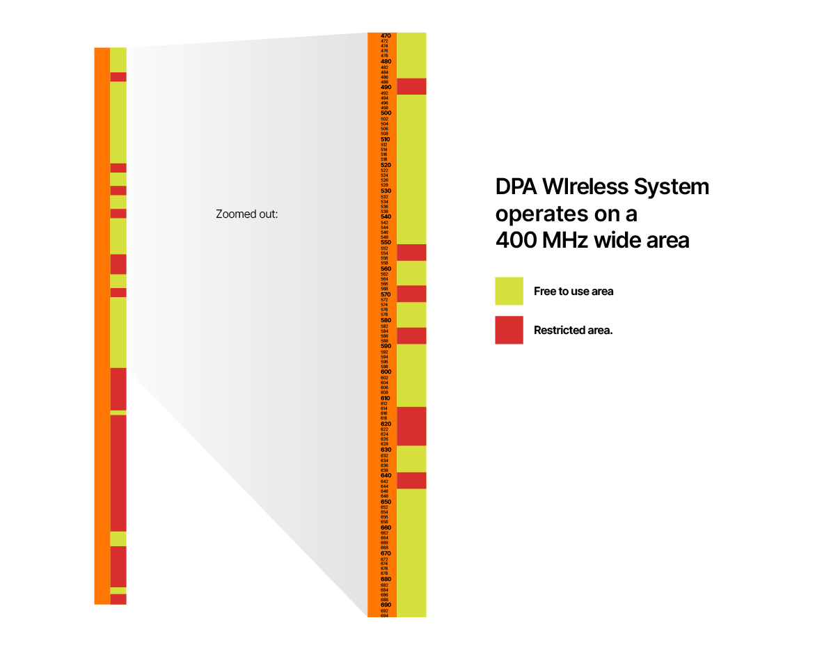
Figure 4.04. Bandwidth of wireless systems.
The most common spacing for low-end systems is approximately 600 kHz: for higher-end systems, around 400 kHz. Then you can run into, for instance, High-Density mode, but this comes at the cost of less AF bandwidth (like 14 kHz), higher latency, less transmission power allowed, and thus less actual reach.
Also, packing more channels at high density most often complicates the intermodulation schemes as more mic transmitters can get in close proximity and cause (very) unwanted dropout/disturbance.
WMAS
Wireless Multichannel Audio System is a recent technology with only one transmission channel (8 MHz in Europe or 6 MHz in the Americas). It is a two-way system with both transmission and reception. The reception can be used for In-Ear-Monitors (IEM). An 8 MHz channel offers a capacity of up to 32 channels out and 32 channels in. If fewer channels are used, the audio quality can be raised, or the bandwidth can be limited. So, the final quality of the signal (frequency range, noise, latency) sets the limits to the system’s channel capacity. The max power is 50 mW. The bidirectional nature of WMAS means that a single bodypack can simultaneously be used for wireless IEMs and microphones or instruments.
The system is primarily for indoor use, as the reception depends on a reflective field of radio waves. Sennheiser and Shure introduced WMAS.
Hybrid systems
Some wireless brands/systems use combined analog and digital techniques (Wisycom, Lectrosonic). For instance, the signal is converted into the digital domain for signal processing in the transmitter and then converted back to analog for the modulation of the carrier. At reception, the signal is again converted to digital information.
The main advantage of utilizing digitalization in the transmitters is making advanced companders with very good audio quality. This is done while preserving the smaller RF bandwidth occupation, keeping the latency to almost zero ms, and going closer to the noise floor of the surrounding RF environment. Typically, a digital system needs at least 14-15 dB of headroom from the noise floor whereas, for instance, the Wisycom transmission systems can go as close as 3-5 dB to the noise floor and thus give a higher security for a stable RF signal even in very rough and dense RF environments.
The above also caters to a more extended “real” reach of the transmission as you are not running out of transmission power vs. noise-floor, as is the case with digital systems.