Immersive/object-based audio recording techniques
Audio formats have developed over time. Starting with narrow bandwidth mono, moving on to various versions of two-channel stereo and finally to full-band, multi-channel immersive audio. The sound is reproduced in many ways, ranging from personal headphones to multi-channel systems in cinemas or other big venues. Immersive audio can be described as a group of recording- and reproduction formats that involve more than a basic two-channel stereo
Immersive audio encompasses all surround formats:
- Channel-based formats reproduced in 5.0/5.1*), 7.1*), 9.1*), etc.
- Formats that include height information, either channel-based or object-based
*) the .1 indicates an individual sound channel that only contains a fraction of the full frequency range, namely the range from 20 Hz to 120 Hz.
There are many ways to record immersive audio. In this article, you will find descriptions of microphone setups for the majority of immersive audio formats. It is important to define the listening setup before selecting the recording setup. In broadcast and in music production, the starting point is the ITU-775 standard listening configuration.
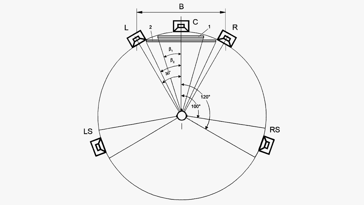
Coincident arrays vs. spaced arrays
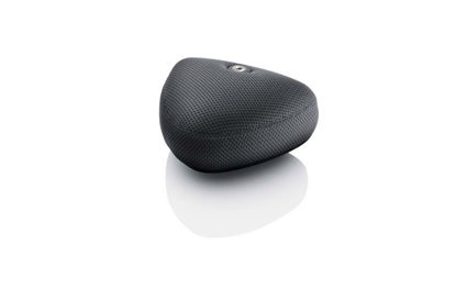
A microphone array is just a physical arrangement of microphones. The array may consist of individual microphones mounted on one single microphone stand or perhaps on several stands or holders. In some cases, the microphones are built into one single unit (like the 5100 Surround Microphone).
In a coincident array, the microphones are mounted extremely close to each other. In principle, all microphones in this type of array receive sound simultaneously.
In the coincident technique, localization cues are based only on level differences between signals. This technique can create proper localization accuracy but will, to some degree, lack envelopment and have a small sweet spot (in two dimensions: left/right and front/rear). The advantage of a coincident array, however, is that it is compact, portable and mono compatible. It is easy to down mix the channels to one single mono channel without coloration from comb filtering and other artefacts.
A spaced array creates a three-dimensional enveloping audio sensation by providing an adequate amount of decorrelation between the signals (localization cues are based on time-of-arrival differences). When adapting the microphone placement (distance and angle) to the sound field, spaced arrays still provide proper localization accuracy.
The spaced techniques, in general, give a nice, large sweet spot and give listeners the sense of an enlarged and enveloping sound stage in a larger listening field. The disadvantage is their size and, in some situations, setup time. In addition, it is not advisable to collapse the signals to a mono signal – instead, one signal can be used.
| Envelopment | Size of listening area | Size and portability | Localization accuracy | |
|---|---|---|---|---|
| Coincident arrays | - | - | + | + |
| Spaced arrays | + | + | - | - |
5.x
The basic and simple setup for channel-based 5.x (5.0/5.1/5.2) surround sound is the application of five microphones in a spaced array. There are different ways to select and arrange the microphones; it depends on many factors like the acoustic qualities of the recording room (i.e. a concert hall/jazz club/church), the layout of the sound sources present, the directivity of the microphones applied, or maybe, just taste. The setups may vary from strictly mathematically-calculated, psycho-acoustically verified to more "feel-like" configurations.
One way of thinking about the coverage of a 360° circle around the listening position is to consider each two neighboring microphones as a stereo pair. Each pair covers a specific segment of the circle. Sometimes the segments overlap, sometimes they "underlap". Another way to look at it, is to consider the frontal microphones as providing the main soundstage and the rear microphones establishing a sense of surround/atmos.
The following setups are not exhaustive but can be seen as inspiration and are examples of best practice:
The omni-based surround array
Five omnidirectional microphones arranged in a spaced array provides a good tonal balance. The low-frequency content is reproduced very convincingly. This setup also provides an excellent envelopment – when reproduced, the listener is surrounded by sound. The drawback of this setup can be the lack of isolation between channels.
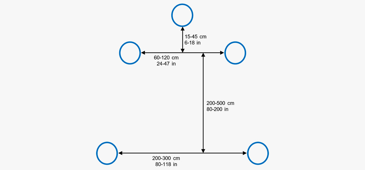
The three frontal microphones – often called the frontal triplet – are arranged as a Decca-Tree. The positions are chosen in accordance with the optimum recording angle of the given sound source.
The position of the rear microphones is chosen independent of the surrounding soundfield. Normally, the rear microphones should not be placed too far from the front microphones. If the distance is too large, the delay may become audible. Furthermore, some directivity might be preferred for the surround pickup. This can be provided by acoustic pressure equalizers (APEs), which ensure directivity at higher frequencies but keep the advantages of the omnis, for good low-frequency response.
A starting point for this setup could look like this:
L-R 60-120 cm (24-47 in)
L-C 30-60 cm (12-24 in)
R-C 30-60 cm (12-24 in)
C-LR 15-45 cm (6-8 in)
Front-Rear: 200-500 cm (80-200 in)
LS-RS: 200-300 cm (80-118 in)
Distance between the outer frontal microphones: 60-120 cm (24-47 in). The wider the width of the source, the narrower the spacing of the mics should be. The center microphone is approximately 15-45 cm (6-8 in) in front of the L/R-pair.
The two rear microphones are placed 2-5 m (80-200 in) behind the frontal triplet. The distance between the rear microphones should be in the range of 2-3 m (80-118 in). As mentioned, APEs can be used to avoid frontal impulsive sounds being reproduced by the rear channels.
The Scottish sound engineer, recording specialist and lecturer, Michael Williams, has done intensive studies on Multichannel Microphone Array Design (MMAD). Look up the literature from Michael to find a precise setup for any given situation. Two publications are mentioned below and further references can be found there.
Literature:
[1] Williams, Michael; Guillaume Le Dû: Multichannel sound recording, Multichannel Microphone Array Design (MMAD). 2010.
[2] Williams, Michael: Microphone Arrays for Stereo and Multichannel Sound Recording Vol II. ISBN 978-88-7365-104-8. Milano 2013.
The cardioid-based surround array
The five cardioid (directional) mic array has the advantage of higher channel separation compared to the omni-based array. To provide the correct coverage in the spaced array, the microphones can be placed closer to each other, creating a smaller array. Of course, this can be taken to the extreme by arranging the microphones in a coincident configuration.
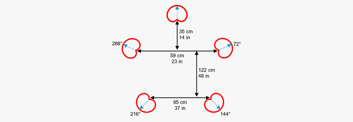
Example: A cardioid-based, 5-channel setup, providing equal coverage of all segments on the circle.
The Wide Cardioid Surround Array
The Wide Cardioid Surround Array (WCSA), introduced by Mikkel Nymand, provides equal timbral qualities, a high degree of envelopment and good low-frequency properties.
To obtain the desired sound character (and to enhance the listening position from a sweet spot to a sweet area), the five signals should be decorrelated. This means the microphones must be placed at an adequate distance from each other. On the other hand, the signals should not be too different (distant) from each other. If this happens, the resulting sound will not be coherent.
Omnidirectional microphones are often preferred for spaced arrays. This is due to their natural sound color and their ability to blend direct signals with room timbre. Wide cardioids (also named sub-cardioids) have a slightly more directional quality, which gives more ambience control and improved front imaging and localization accuracy.
The surround array initiated by Geoff Martin and Jason Corey, uses an omnidirectional and a cardioid to create wide cardioid characteristics. By focusing on preventing inter-channel interference, the microphone pairs were spaced L-C 60 cm (24 in), R-C 60 cm (24 in), Front-Rear 60 cm (24 in) and LS-RS 30 cm (12 in). The rear mics used were upward-aiming cardioids to capture height information.
DPA Microphones adapted this array to use five identical wide cardioid microphones (matched within a very narrow tolerance of ±1 dB on frequency response and sensitivity). Choosing five identical microphones instead of just a specific microphone type keeps the blend natural and leads to a more authentic and uniform reproduction of all channels.
After intense listening sessions and numerous practical tryouts in different recording applications (symphonic music, modern jazz, PA/Live, pop concerts and ambience recording), it has been found that this adaptation tends to work best with a larger spacing, especially of the rear channels. This array creates an intense, dynamic and enveloping sound character.
The recommended distances are:
L-C 60-75 cm (24-30 in)
R-C 60-75 cm (24-30 in)
C-LR 20 cm (8 in)
Front-Rear: 150-200 cm (59-79 in)
LS-RS: 120-150 cm (47-59 in)
Angling L/R: ±15°
Angling LS/RS: ±165°
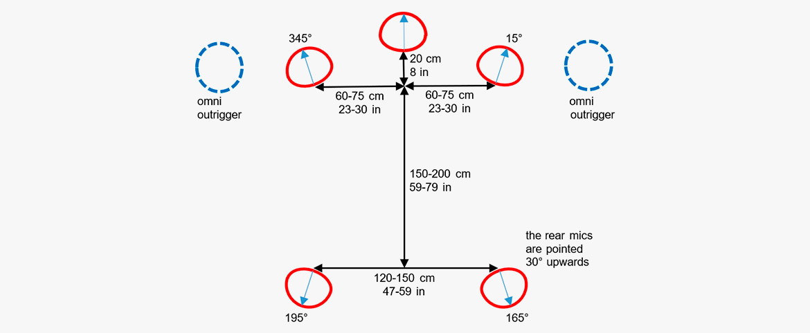
For wide ensembles (or large array-to-source distances), try expanding this array with two left/right omnidirectional outriggers to benefit from the pressure transducers' low-frequency pickup. These microphones are blended with L/R from the array at an appropriate level, offering a beautifully coherent, precise and rich surround sound image.
Soundfield / Ambisonics
In the early 70s, the British engineers Peter Felget and Michael Gerzon invented the soundfield principle later known as Ambisonics (today known as "First Order Ambisonics"). The format is based on a coincident array of microphones. The aim is to facilitate arbitrary microphone orientation in any direction, left/right, front/back, up/down. Basically, the soundfield principle works like MS, by addition and subtraction of the available signals. Two configurations are associated with Ambisonics: A-format and B-format.
The A-format is the physical arrangement of four cardioid microphone capsules and their output: FU (front upper), RU (rear upper), LD (left lower) and RD (right lower). The angles between the capsules are congruent with a tetrahedron, a triangular pyramid.
The B-format is a converted version of the A-format, resulting in a virtual format consisting of three orthogonally-oriented figure-of-eight "capsules"; X (front/back), Y (side), Z (up/down) and one omni (W).
By addition and subtraction, the individual signals can be converted to a directional microphone pointing in any direction. For instance, one omni (W) and one figure-of-eight (X) creates a cardioid pointing in the X-direction.
DPA Microphones formerly produced microphones for the format but does not at present.

Example: B-format components
Optimized Cardioid Triangle (OCT)
OCT is an array designed for the three front channels only. The system offers high separation between left-center and right-center. An additional configuration for the surround channels should be chosen carefully.
A cardioid microphone is used for the center channel placed only 8 cm (3.1 in) in front of two higher-order directional cardioids for left and right channels, pointing outwards. The spacing between the left and right microphones is the key to the desired recording angle. Distances between 40 cm (15.7 in) and 90 cm (35.4) are recommended from the designers, resulting in recording angles from 160° to 90°.
One or more pressure (omnidirectional) microphones can be added to the system to compensate for the missing low frequency from the pressure gradient capsules of the cardioids.

Example: The OCT2 variation suggests that the center microphone should be placed 40 cm (15.7 in) in front of the left/right microphone base line, giving larger time differences and spaciousness more like the Decca Tree.
Double MS
A time coincident, compact and adjustable surround configuration.
The Double MS setup is a time coincident, compact and adjustable configuration for surround sound/immersive sound. Two cardioids microphones and one figure-of-eight microphone are used. Alternatively, the setup can be created from four cardioid microphones.
The principle of the Double MS technique is a forward and backward pointing MS set, sharing the same side microphone. As in a standard MS setup, the side microphone is positioned with the in-phase side pointing left so only three microphones are needed. In this setup, processing/mixing is necessary to create the final format. As always with MS setups, two different transducer types are applied to provide the mid-information (cardioid microphones) and the side-information (bi-directional microphones). There is the risk of different frequency and phase responses of sound reproduction from the sides or the front.

This is how the channels are obtained:
Center = Mfront
Left = Mfront + S
Right = Mfront – S
Left surround = Mrear + S
Right surround = Mrear – S
The amount of each signal is adjusted for correct spatial distribution, especially regarding the frontal image. Typically, the L/R width is produced a little wider compared to standard MS for two-channel stereo.
The Double MS technique can be attained by using four identical – evenly matched – 4011A or 4011C Cardioid Microphones angled on the horizontal plane at 0°, 90°, 180° and 270° respectively. The membranes should be arranged above each other for best time alignment in the horizontal plane.
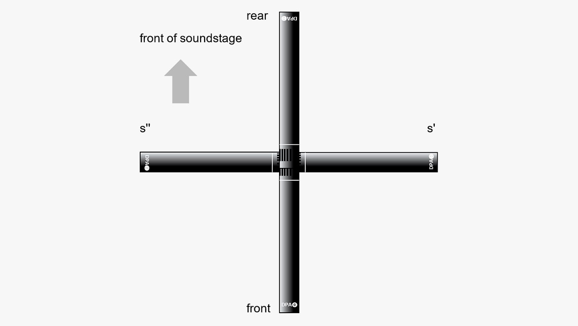
Mfront = Cardioid front
S = S’ (Cardioid left) – S’’ (Cardioid right) *)
Mrear = Cardioid rear
*) In practical recording using a mixer, just pan "cardioid left" to the left and pan "cardioid right" to the right + invert the phase (swap pin 2 and 3). The "dirty" way to do this is by using a Y-summing cable and invert the XLR-connector for the cardioid right.
Fukada Tree
The Fukada Tree is a Decca Tree array, but with five cardioid microphones and two additional omnidirectional microphones as outriggers to blend in between the front and rear channels. This setup was designed by Akira Fukada in 1997.
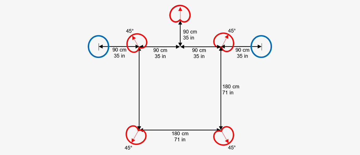
The choice of cardioid microphones improves the channel separation, and the backward-oriented rear cardioids also minimize leakage of direct frontal sound to the rear speakers.
Omnidirectional microphones are often preferred in Decca Tree configurations for music recordings due to their natural sound color and full frequency bandwidth. The two omni outriggers serve this very important component in the Fukada Tree array.
Since first announcing the Fukada Tree arrangement, Akira Fukada has designed a number of positioning modifications to improve front localization, but his choice of microphones remains constant and he continues to use DPA mics for their transparent feel.
Hamasaki Square
The Hamasaki Square consists of four bi-directional microphones arranged in a square.
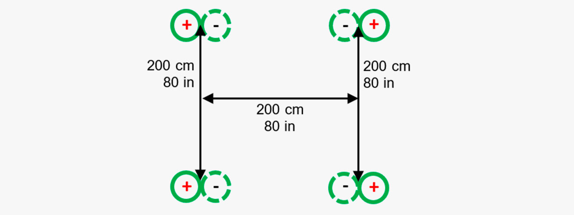
The Hamasaki Square is designed for capturing the ambient/diffuse part of a surround sound recording. It is a four-mic square with 1.8-2 m (5.9-6.6 ft.) between the figure-of-eight microphones, which are routed to left, right, left surround and right surround at an appropriate level compared to the front array. The figure-of-eight microphones are pointed with their in-phase sensitive directions against the sides and with their nulls to the direct sound.
Compared to other systems for ambiance recording, this system is the least sensitive regarding the distance between the main array and the ambiance array.
The setup is defined by the Japanese sound engineer Kimio Hamasaki.
Immersive audio with height
Setups developed for traditional surround recordings (like 5.1) have proven to work very well. However, adding height to these recordings is interesting as it may also add new dimensions to the perceived experience.
The challenge is, however, how to add upward-directed sound images, without changing the perceived localization of horizontally positioned sound sources, meaning minimizing vertical inter-channel crosstalk. This leads to considerations regarding vertical time and level differences. The spacing of vertical microphones needed for decorrelation must also be considered. Finally, how can we avoid comb filtering in the unavoidable downmix?
When height information is added in the right way, the perceived envelopment created by the sound is enhanced. More than that, good practice has demonstrated enhancement of the perceived precision when localizing the sound sources, even in the horizontal plane!
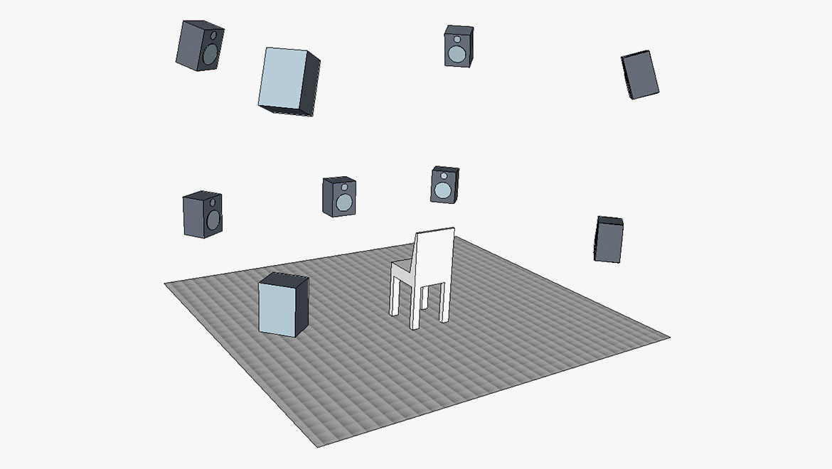
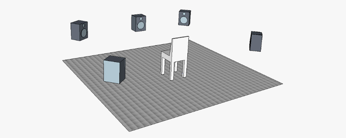
Examples: A standard reproduction setup for immersive audio containing height information is 9.1, which is a standard 5.1 ITU 775 layout with additional upper-layer speakers above the left, right, left surround and right surround speakers. The height of the additional four speakers should provide a vertical listening angle of approximately 30°.
Dr. Hyunkook Lee of Huddersfield University (UK) and his research group have provided a lot of theoretical and practical information on the perceived sound imaging.
One important factor he found is that the precedence effect (the effect that the first arriving sound determines the direction) does not work in the vertical plane. Hence, it is worth looking at level differences. When playing back the same sound in the lower and the upper loudspeaker, it was found that the presence of higher frequencies and transient signals pulls the localization towards the upper loudspeaker [2,3].

Example: To keep the localization in the horizontal plane, it was found the upper signal should be attenuated by at least 7
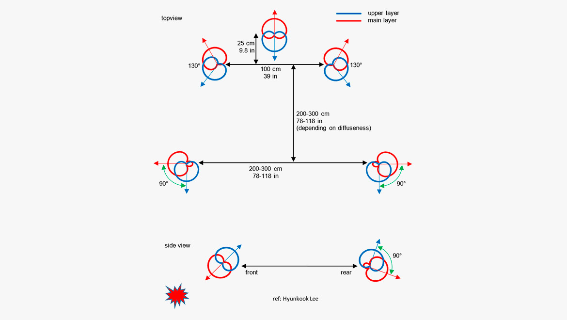
These findings have led to the microphone setup shown below. It consists of eight cardioid microphones and two supercardioid microphones.
The orientation of the microphones is such that there is a minimum of frontal sound entering the upper layer of microphones. In general, any upper-layer microphone should receive as little sound as possible that contains sound from the primary horizontal sources and sources below the horizontal plane.
[1] Wallis, Rory, and Lee, Hyunkook: The Effect of Inter-channel Time Difference on Localization in Vertical Stereophony. Journal of the Audio Engineering Society, Vol. 63, No. 10, October 2015.
[2] Lee, Hyunkook, and Gribben, Christopher: Effect of Vertical Microphone Layer Spacing for a 3D Microphone Array. Journal of the Audio Engineering Society, Vol. 62, No. 12, December 2014.
[3] Lee, Hyunkook: Perceptual Band Allocation (PBA) for the Rendering of Vertical Image Spread with a Vertical 2D Loudspeaker Array. AES Convention 138, Warzawa 2015.
[4] Lee, Hyunkook: The Relationship between Interchannel Time and Level Differences in Vertical Sound Localisation and Masking. AES Convention 131, New York 2011.
IRT Cross
The IRT Cross is designed for ambiance pickup. The setup consists of four cardioid microphones.
The IRT cross is designed for capturing the ambient/diffuse part of a surround-sound recording. It is a four microphone square with 20–25 cm (7.9–9.8 in) between the cardioid microphones, which are routed to left, right, left surround and right surround in an appropriate level compared to a front array.
The IRT Cross is normally positioned a couple of meters behind the main array. However, it should not be placed too far away as there may occur timing problems (like an echo) in the reproduced signal. The optimal placing of the IRT Cross is a balance between getting enough ambiance while at the same time avoiding echo.
Object-Based audio
For years, the most enveloping loudspeaker-reproduced sound has been channel based. One channel is for mono, two channels are for stereo and six channels are for 5.1 surround-sound (or 24 channels for NHK 22.2).
Conventions regarding the placement of the loudspeakers for each format have been the backbone of the sound design. Inter-channel panning by the aid of delay- or level adjustments has been the tool for the placement of sources of the sound scene. The finished product would be contained in a fixed number of channels; even though the program material originally was recorded on a huge number of audio tracks, the final product would fit into a specific number of channels, one for mono, two for stereo, etc.
The Object-Based Audio (OBA) is somewhat different. A "sound object" can be recorded on one or more tracks. Along with the audio goes the metadata that tells where to position the sound in the soundstage.
An object could be a voice recorded in mono. If the producers intend to let the voice come from the right of the soundstage, then the metadata of the voice recording contains the coordinates of this sound. The voice is for this reason recorded as a stereo track. Then the metadata of these stereo tracks provides the data for the positioning.
In principle, an object may also stem from an ambisonic recording or any other format. Therefore, an AV program with OBA is built up from a string of objects, like voice recordings, music, ambient sounds, special sound effects, etc. Each object will contain metadata on when and where to be reproduced.
OBA has already found its way to the cinema (Dolby Atmos and the like). However, it is the intention to bring it into broadcast as well, and many experiments have been carried out. In addition, virtual reality (VR) is an obvious target for OBA.
Why?
The general idea is to leave a higher degree of freedom to the listener, especially in broadcast. Now it is possible to emphasize a single object. If a hearing-impaired listener wants to level up the dialog, this is a possibility, if you record the dialog as an object. You can also change the language of the commentary, if you allocate each language to separate objects.
From TV productions like Formula 1 races, we know that special onboard cameras can be selected, if the viewer wants to follow a specific car. The sound of that specific car is an object in conjunction with the image. Specific musical instruments in an orchestra can be regarded as objects. Alternatively, the sound from a concert, recorded at different listening positions can be objects.
Another argument for OBA is that almost any reproduction format is valid. The downmix is optimized depending on the number of channels and their positions available for the playback (as long as the number of channels is at least two). Binaural reproduction is also allowed for.
Microphones?
The basic idea is that the sound engineer can use the kind of microphones that he likes. There is not necessarily a demand for specific microphones, microphone configurations or microphone brands. The special requirement goes on the production equipment, that can establish the metadata and of course to the formats that carry the complete information.
Suggested microphones & accessories
Omni-based surround array
- 4006A Omni Microphone
- 4006C Omni Microphone, Compact
- 5006A Surround Kit of five matched 4006A microphones, clips and windscreens in Peli™ case
- S5 Surround/Decca Tree Mount
Cardioid-based surround array
- 4011A Cardioid Microphone
- 4011C Cardioid Microphone, Compact
- S5 Surround/Decca Tree Mount
Wide cardioid surround array (WCSA)
- 4015A Wide Cardioid Microphone
- 4015C Wide Cardioid Microphone, Compact
- 5015A Surround Kit of five matched 4015A microphones, clips and windscreens in Peli™ case
- 4006A Omni Microphone
- 4006C Omni Microphone, Compact
- 3506A Kit of two matched 4006A microphones, clips and windscreens in Peli™ case
- S5 Surround/Decca Tree Mount
Optimized cardioid triangle (OCT)
- 4011A Cardioid Microphone
- 4011C Cardioid Microphone, Compact
- 4018A Supercardioid Microphone
- S5 Surround/Decca Tree mount
Double MS
DPA does not provide any figure-of-eight microphones. We suggest the Schoeps MK8 with CMC6 preamp. However, if you want to try this setup with DPA microphones, we suggest you substitute each figure-of-eight microphone with two cardioid microphones:
- ST4011A Stereo Pair with 4011A Cardioids
- SB0400 Modular Stereo Boom
- UA0836 Stereo Boom
Fukada tree
- 4011A Cardioid Microphone
- 4011C Cardioid Microphone, Compact
- 4006A Omni Microphone
- 3506A Kit of two matched 4006A microphones, clips and windscreens in Peli™ case
- S5 Surround/Decca Tree Mount
- ST4011A Stereo Pair with 4011A Cardioids
- SB0400 Modular Stereo Boom
Hamasaki square
DPA does not provide any figure-of-eight microphones. We can suggest the Schoeps MK8 with CMC6 preamp. However, if you want to try this setup with DPA microphones, we suggest you substitute each figure-of-eight microphone with two cardioid microphones:
- ST4011A Stereo Pair with 4011A Cardioids
- S5 Surround/Decca Tree Mount
Immersive audio with height
- 8 x 4011A Cardioid Microphone
- 2 x 4018 Supercardioid Microphone
IRT Cross
- 4011A Cardioid Microphone
- 4011C Cardioid Microphone, Compact
- ST4011A Stereo Pair with 4011A Cardioids
- MMC4011 Cardioid Microphone Capsule
- MMP ER/ES Modular Active Cable
- SB0400 Modular Stereo Boom
- UA0837 Stereo Boom
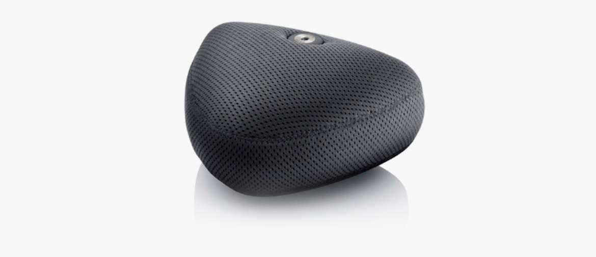
DPA 5100 Surround Microphone
The 5100 Mobile Surround Microphone is a plug-and-play solution.
One unit contains three directional (DIP-MIC, directional pressure microphones), coincidently arranged frontal microphones. The rear channels are recorded by a spaced pair of two omnidirectional microphones. The unit also provides an LFE-output. All channels are calibrated to unity gain. The LFE is reduced by 10 dB, according to the standard.
The 5100 is much appreciated in film production for 2nd unit work.
References
[1] Gasull Ruiz, Allejandro: A Description of an Object-Based Audio Workflow for Media Productions. Convention Paper 9570, AES 140th Convention, Paris 2016.
[2] Steven A.: Object-based audio for television production. IBC 2015.
[3] Messonnier, Jean-Christophe et al.: Object-based audio recording methods. Conference proceedings, AES 57th International Conference, USA, 2015.
[4] Shirley, Ben et al.: Personalized Object-Based Audio for Hearing Impaired TV Viewers. Journal of the Audio Engineering Society, Vol. 65, No. 4, April 2017.
